First Iris Build
Wednesday 01/24/2018
TL;DR
A few more parts arrived but I’m still waiting on the case.
Notes
Today I got back from Hawaii and a few other parts arrived:
- Keycaps from PimpMyKeyboard
- Strip LED
- 470 Ohm resistors
Still waiting on the case pieces which should come within the next few business days. Hopefully I’ll get started on the build this weekend.
The keycaps are just SA profile blanks from SP in the best colors that were available:

Friday 01/26/2018
TL;DR
Case pieces arrived and I prepared and organized them.
Notes
Today the “final” pieces of my keyboard arrived. I put final in quotes because I actually realized one more thing I’m missing: the M2 screws. When you buy the case directly from keeb.io the screws are included but obviously (Or not so obviously) if you get the case laser cut from Sculpteo, they are not. Woops! Luckily they can be purchased from Home Depot so I don’t need to wait on another package arriving.
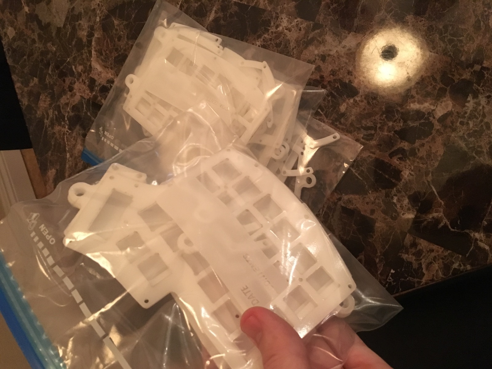
After unpacking the case layers, my heart sunk a little when I saw some ugly burn marks and one side with printed text on it:
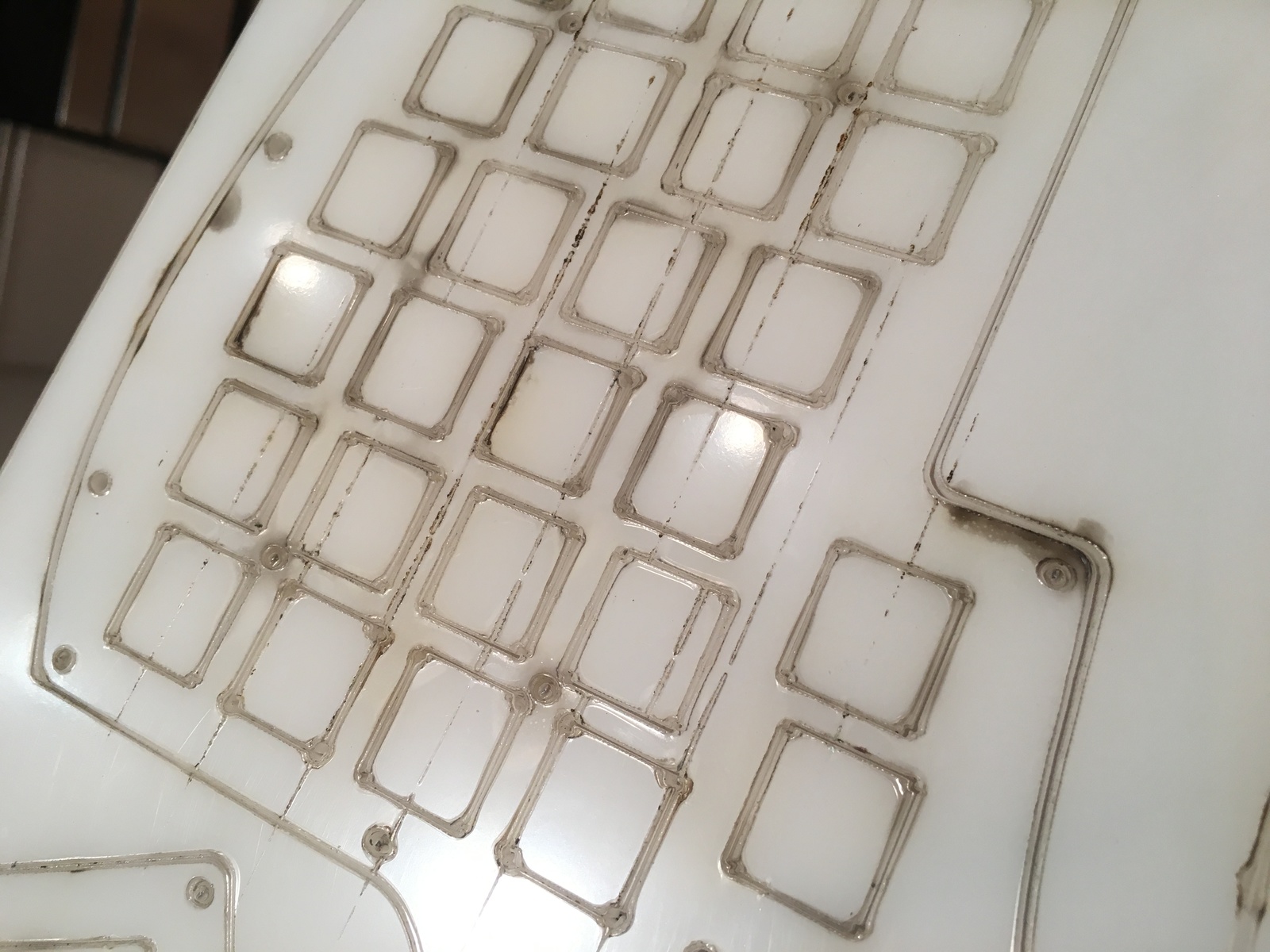
After closer examination, I realized that both sides actually have an adhesive Perspex protective sheet on them which can be peeled off. On one hand I’m quite happy because the Acryllic actually looks very nice once it’s removed. On the other hand, I didn’t plan on having to peel off 64 pieces of adhesive. That being said, it’s still much better than the alternative!
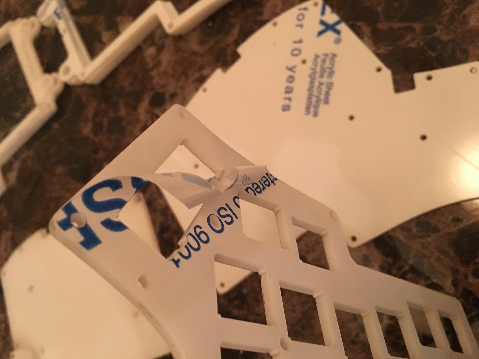
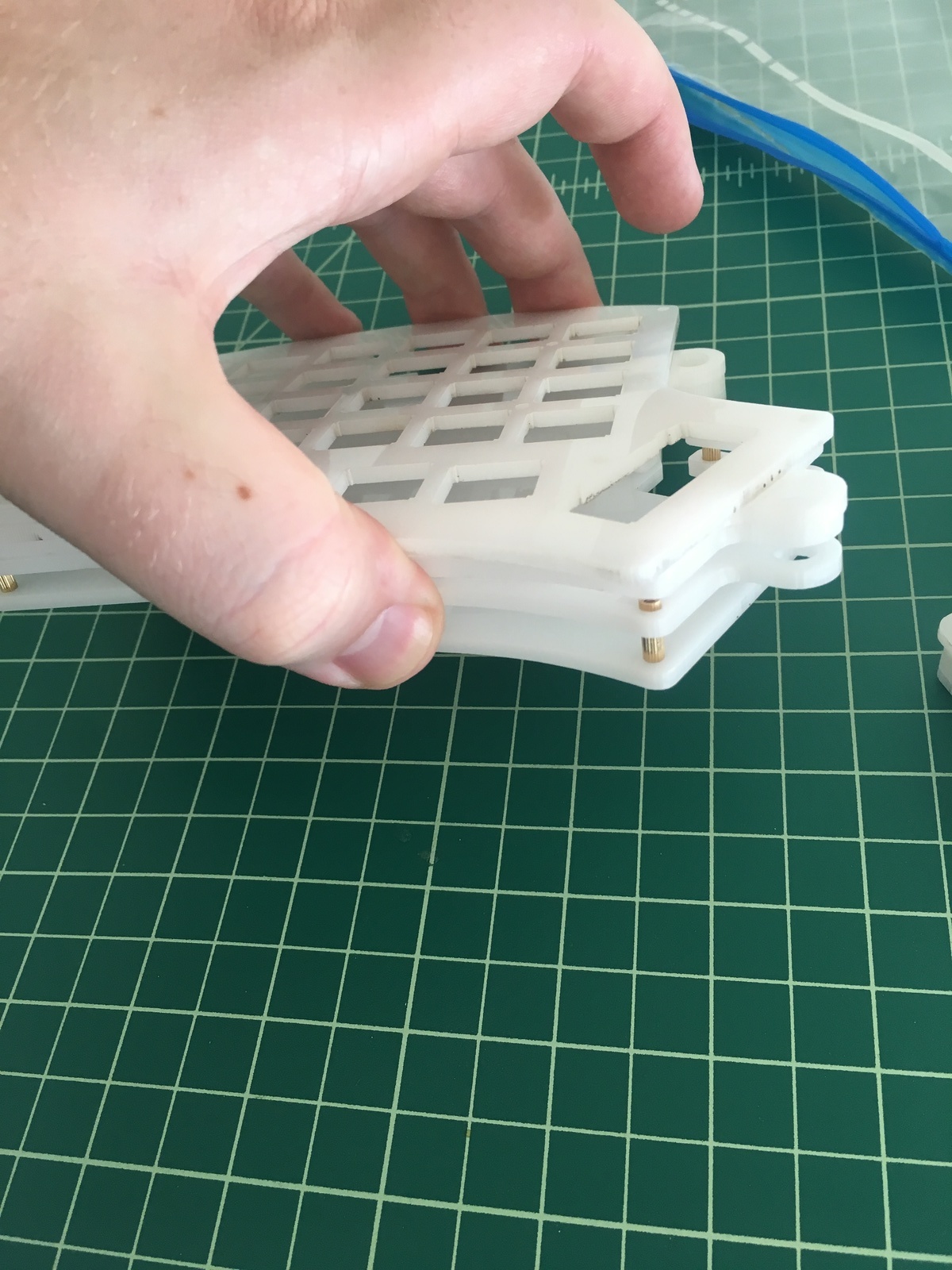
Here’s what the pieces look like after being popped out of their sheets:
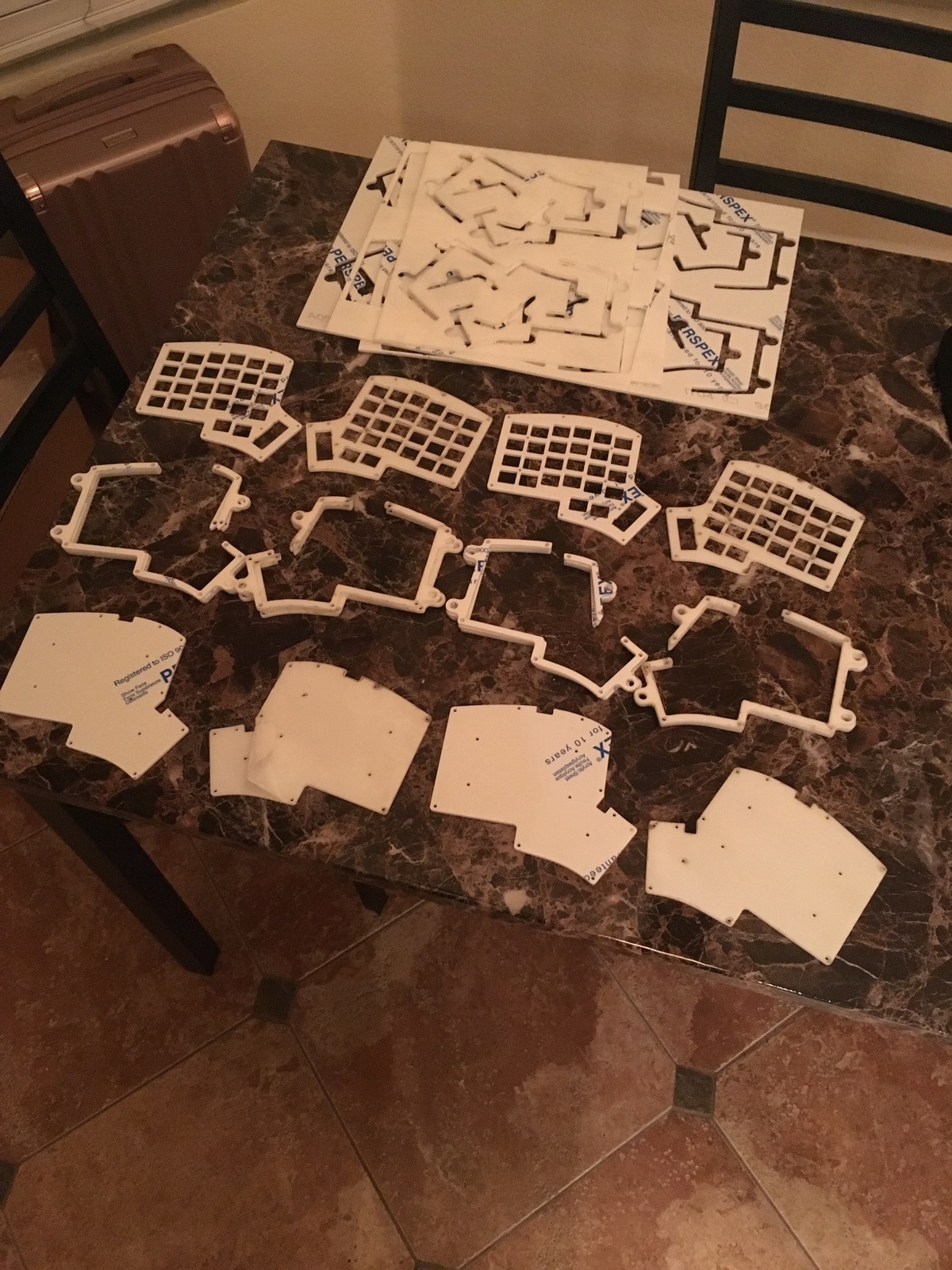
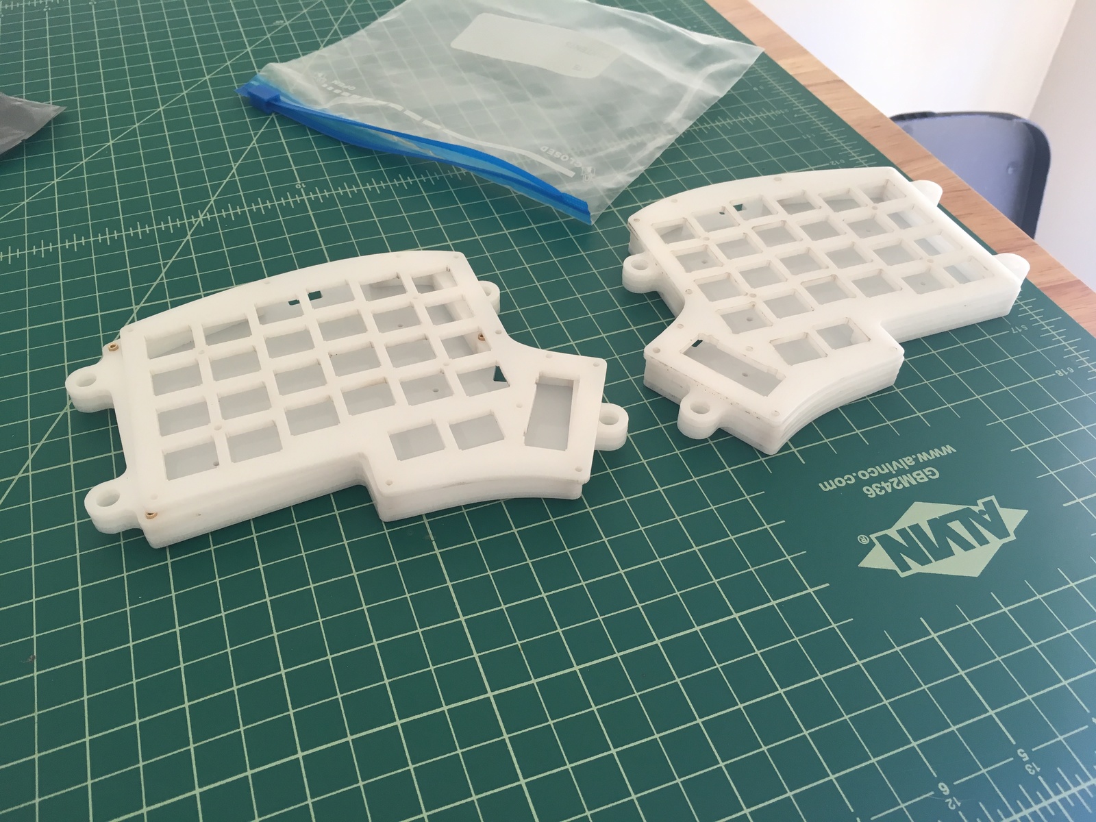
And after removing all of the adhesive and organizing the pieces into separate bags:
Thursday 02/01/2018
TL;DR
Everything has arrived and my workstation is set up.
Notes
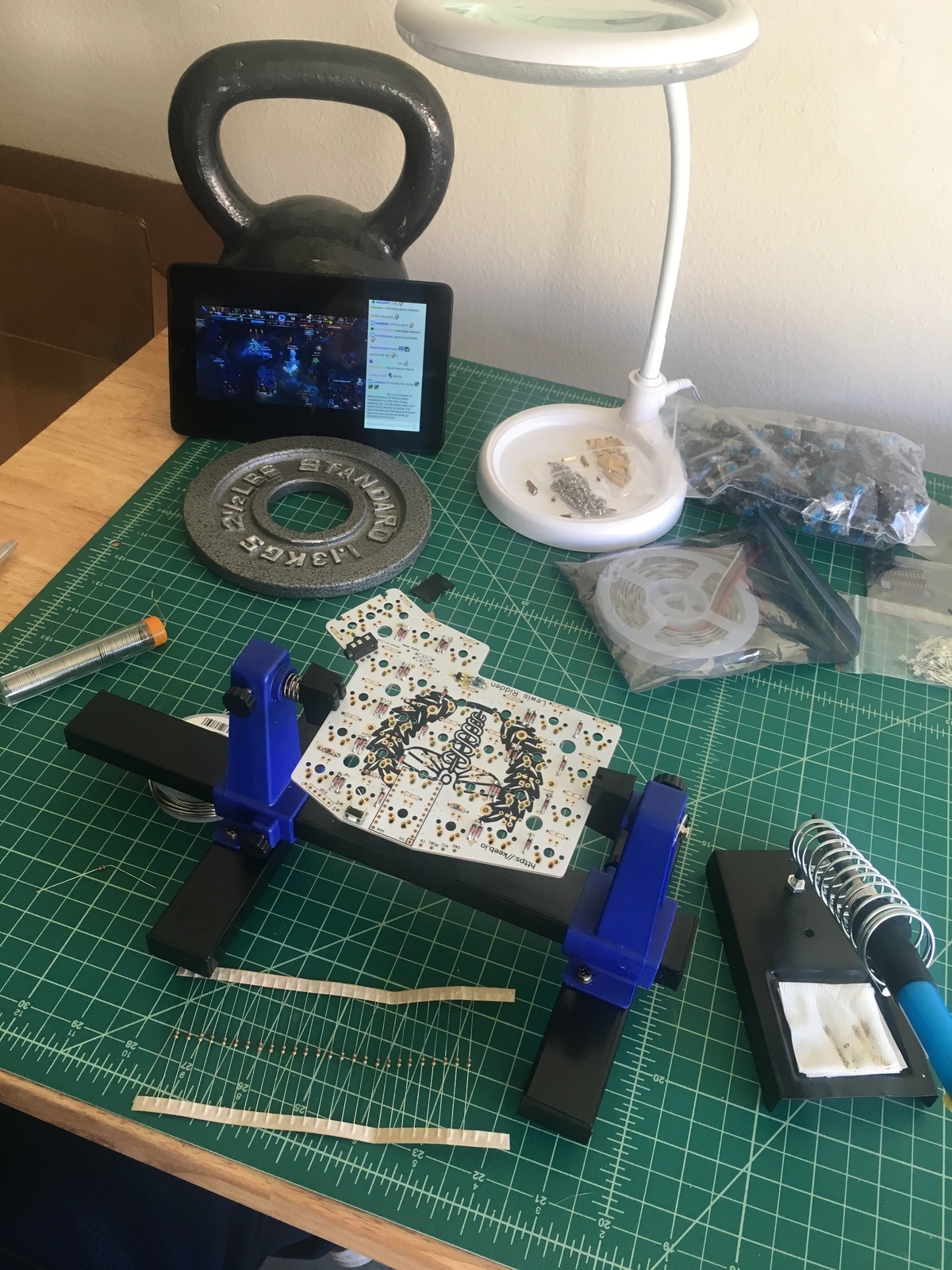
I realized that I needed a couple more tools before I could get started soldering. I bought a lamp and a soldering clamp which both arrived on Monday. I also got a clamp-mounted phone arm so that I can hopefully take some video during the building process.
The M2 screws from keebio also came yesterday so now I officially have all the materials. I think I may actually use leftover Gateron blue switches for the first build. They are PCB mounted which should make things a bit easier. The Kailh box blacks are plate mounted which means it will be easier to accidentally solder them on crooked. The in-switch LEDs also fit better as the Kailhs are meant to be used with smd LEDs.
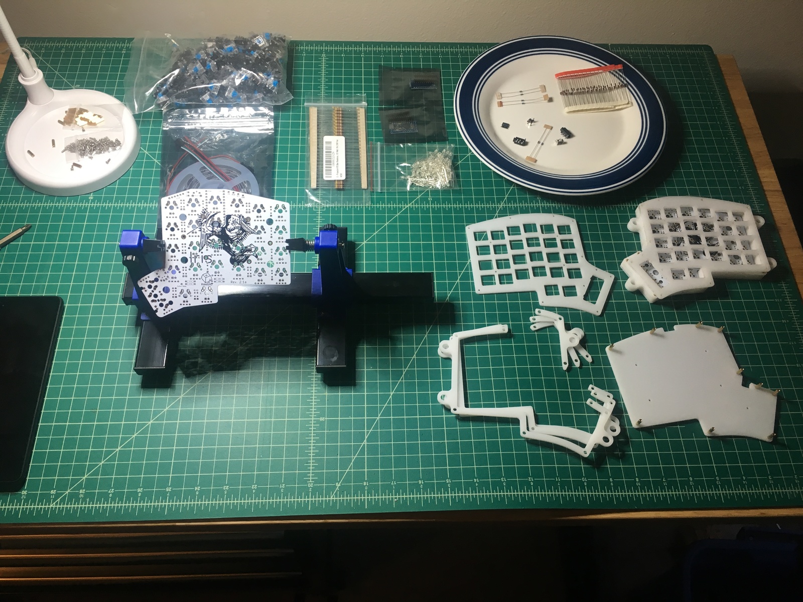
Since I ordered the case from sculpteo and not from keebio, I also made sure I used the correct values and that the case pieces line up correctly, which they do:
Tuesday 02/06/2018
TL;DR
I soldered the TRRS jacks, the reset switches, and the diodes.
Notes
I decided to wake up early and get started on the keyboard today. I got out my soldering tools and straightened up my work area:
I started on the TRRS jacks. I had to use electrical tape to keep them in place while I soldered the pins.
After soldering on the reset switches, I actually wished I did the same as one of them shifted slightly while I was soldering it so it’s a bit crooked. It should still fit in the case just fine so I decided to leave it instead of desolder it and fix it.
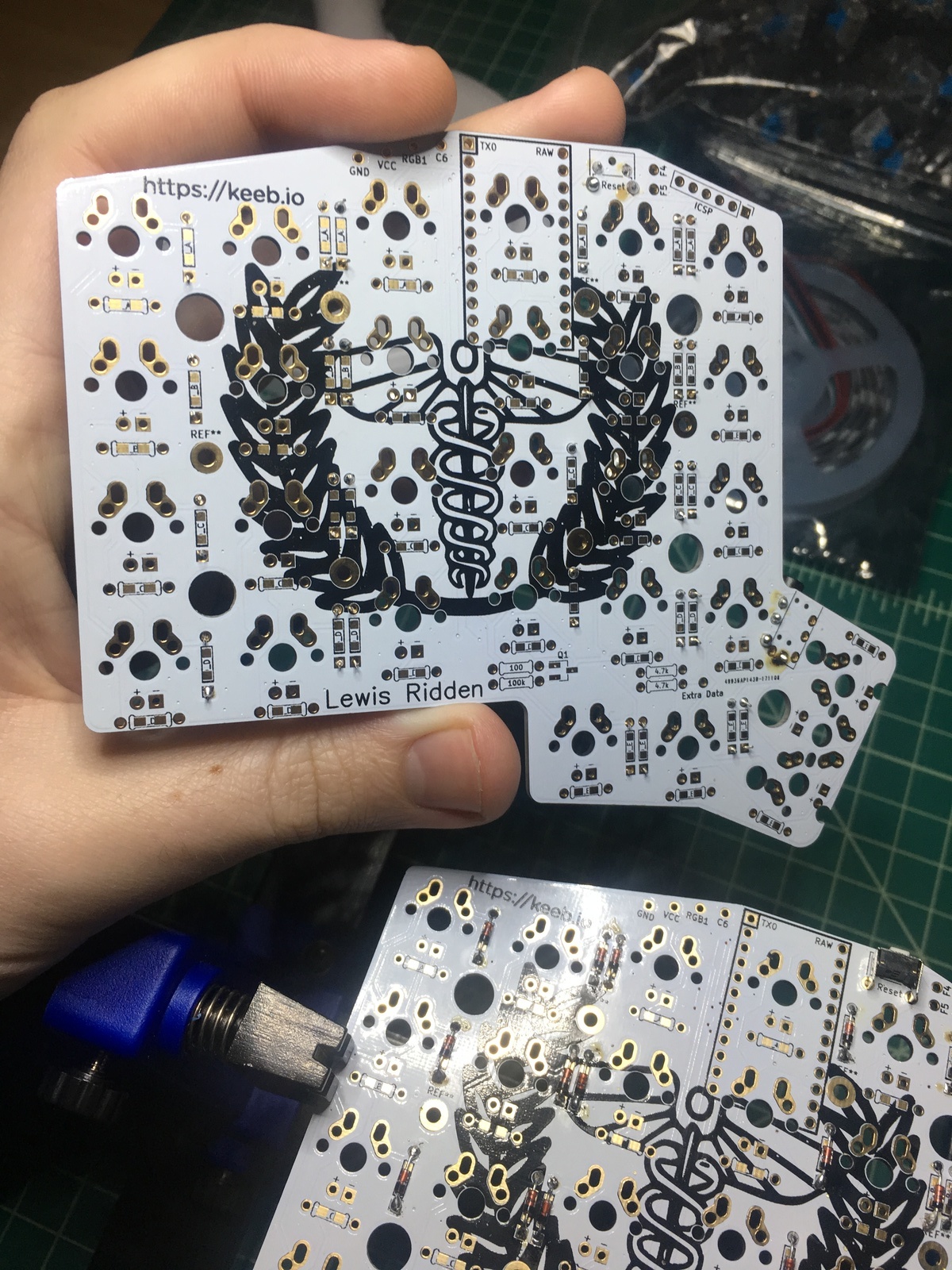
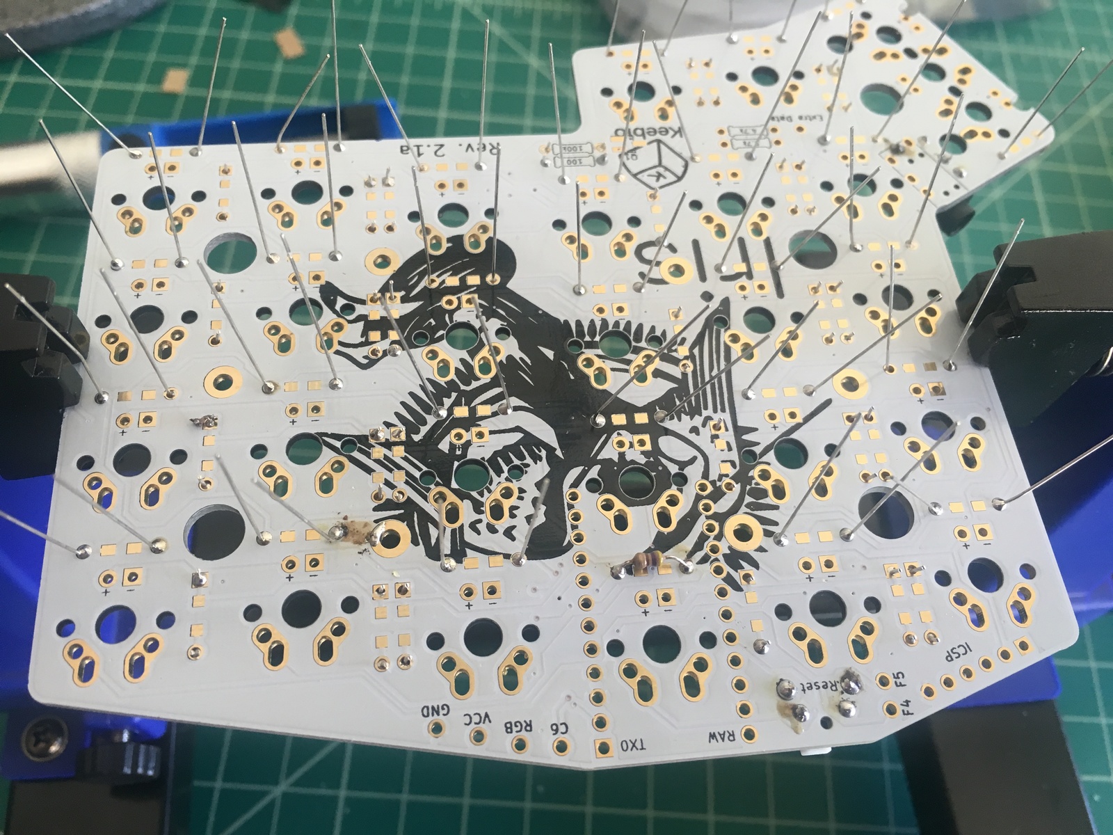
For the diodes, I pulled 28 of them off of the strip and placed them in one PCB. I soldered all of them and then did the same for the other side.
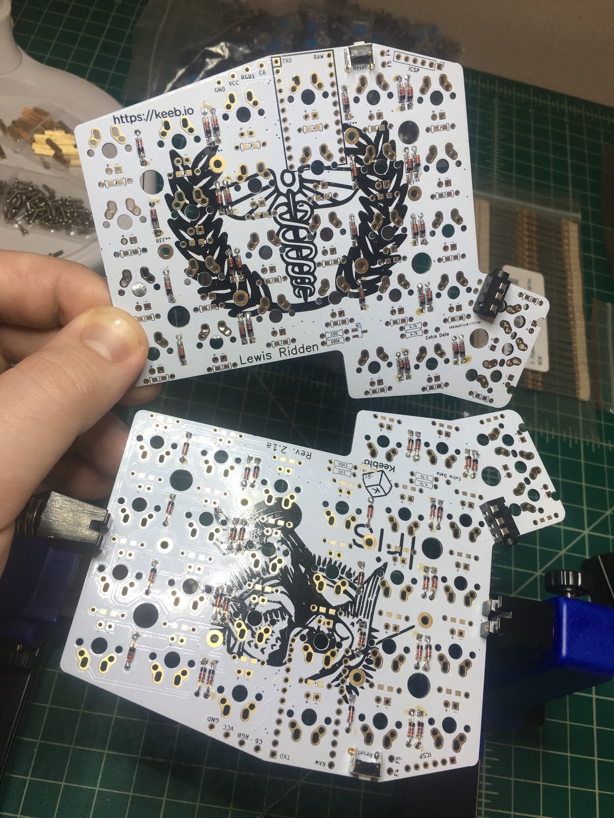
I still need to clip the diode legs but I’ll get to that when I continue on the board later.
Next up is to solder on the MOSFET, I2C resistors, and resistors for MOSFET.
Wednesday 02/07/2018
TL;DR
I soldered the I2C resistors, MOSFET, and LED support resistors, then realized my 470k resistors are too big.
Notes
I got up early again today to try and knock out another big chunk of the build.
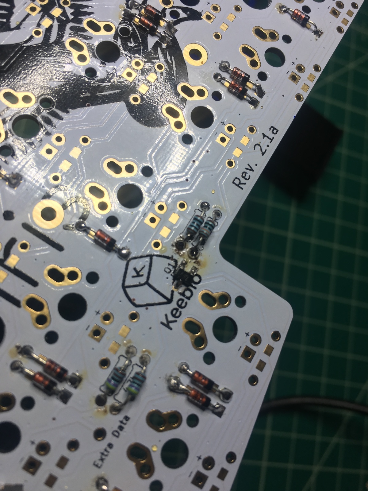
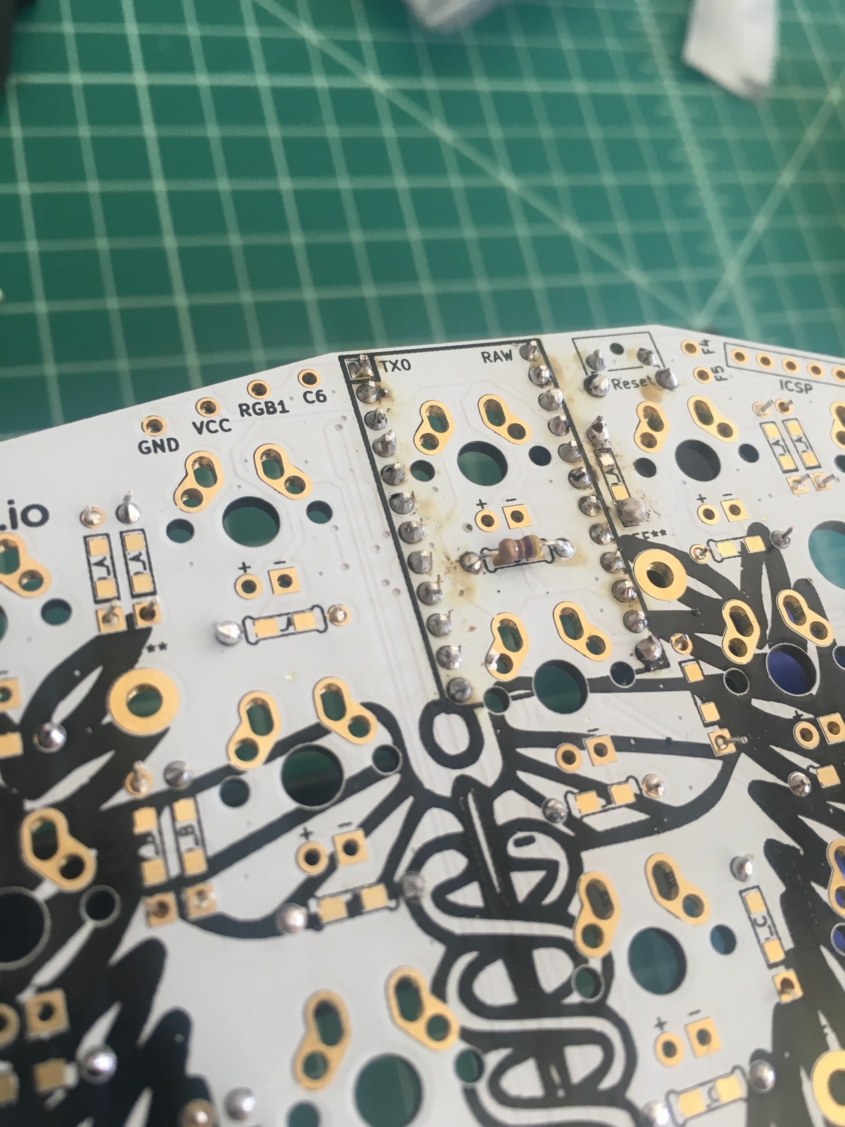
First thing I had to do was clip the diode legs which I didn’t do yesterday:
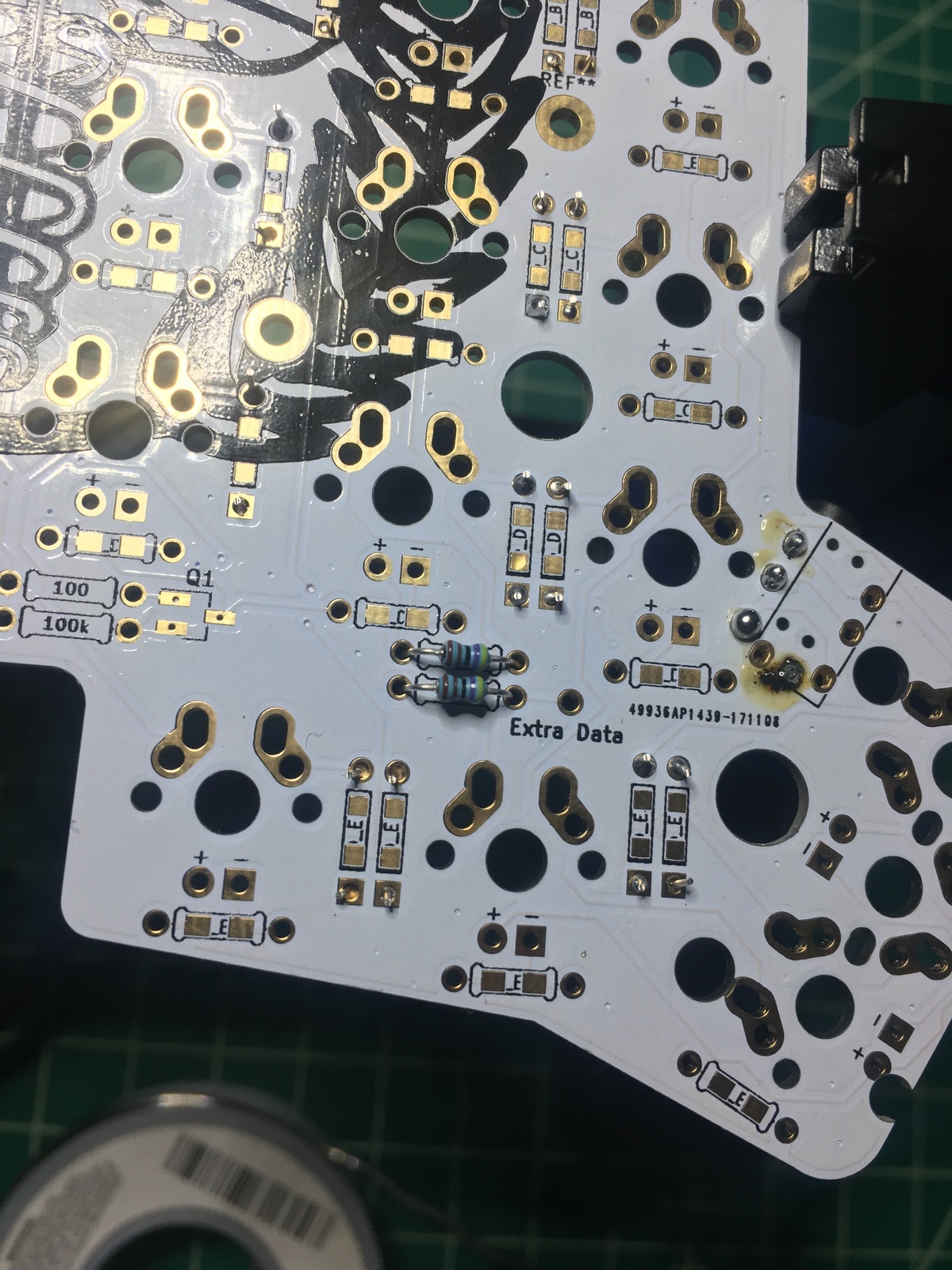
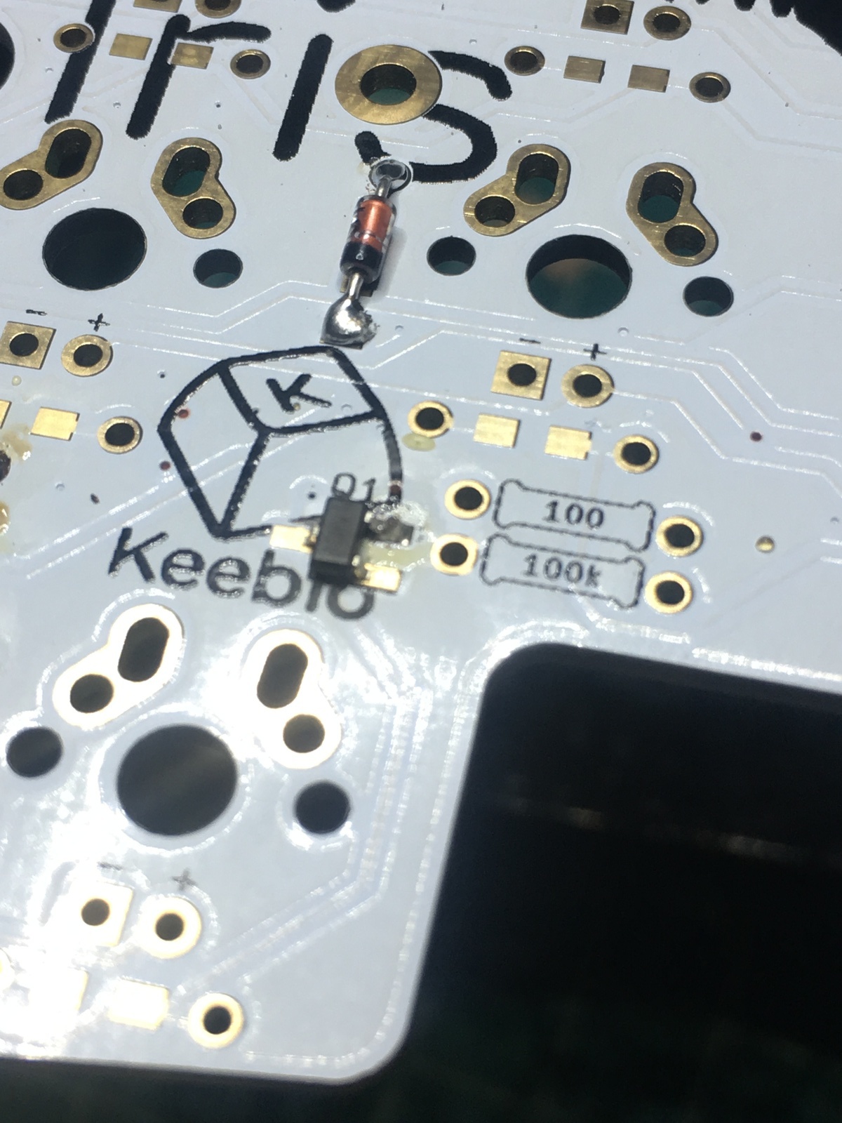
I added the I2C resistors first which is pretty straight forward; I put them on the left half.
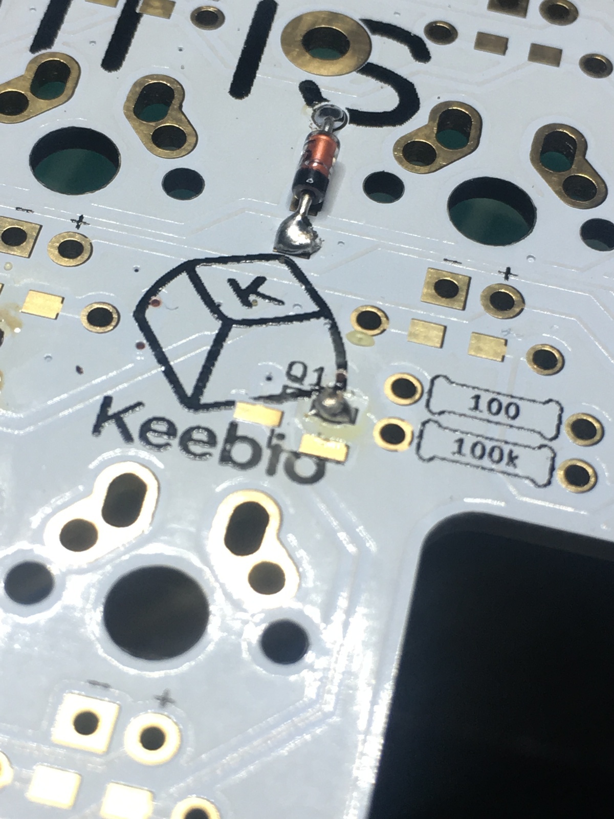
The MOSFET went on pretty easily on the left half but was a pain in the balls on the right. I followed the recommendation of applying some solder to one of the pads first, then heating it up and positioning the MOSFET component, then soldering the other two pads. I have a cheapo soldering iron and the solder kept balling up on the tip of the iron instead of transfering to the pad. The process:

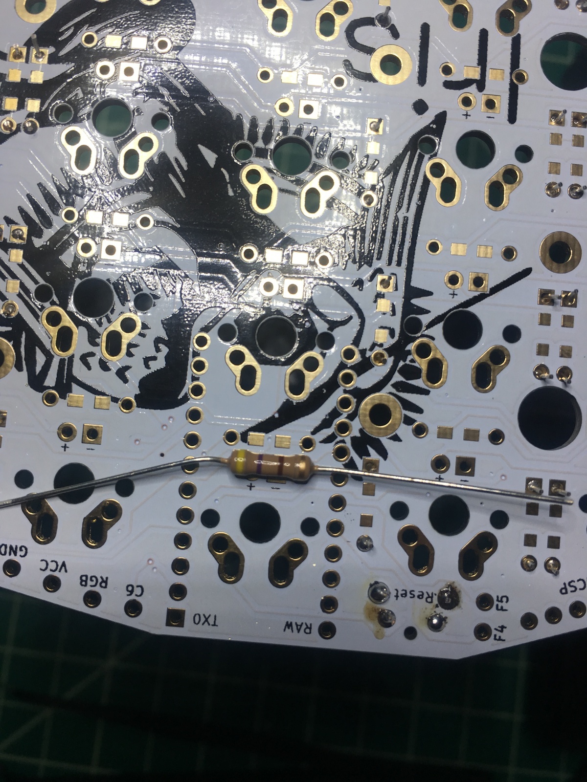
Lastly, I added the LED support resistors which wasn’t too bad:
I was going to move on to the switch LED resistors until I realized that the 470 resistors I bought are too big so I need to order smaller ones.
Sunday 02/11/2018
TL;DR
The board is basically done; I just need to create my own QMK keymap and wait for the correct M2 spacers.
Notes
With Sharae out of town this weekend and the replacement resistors arriving on Friday, I decided to just sit down and knock out the rest of the build today. So, I got set up with some HGC playing on my Kindle:
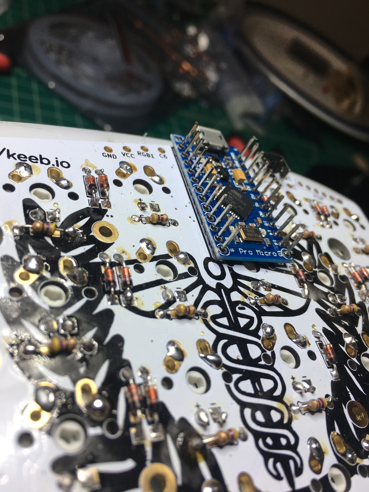
The first order of business was adding the switch LED resistors. These were pretty straight forward:

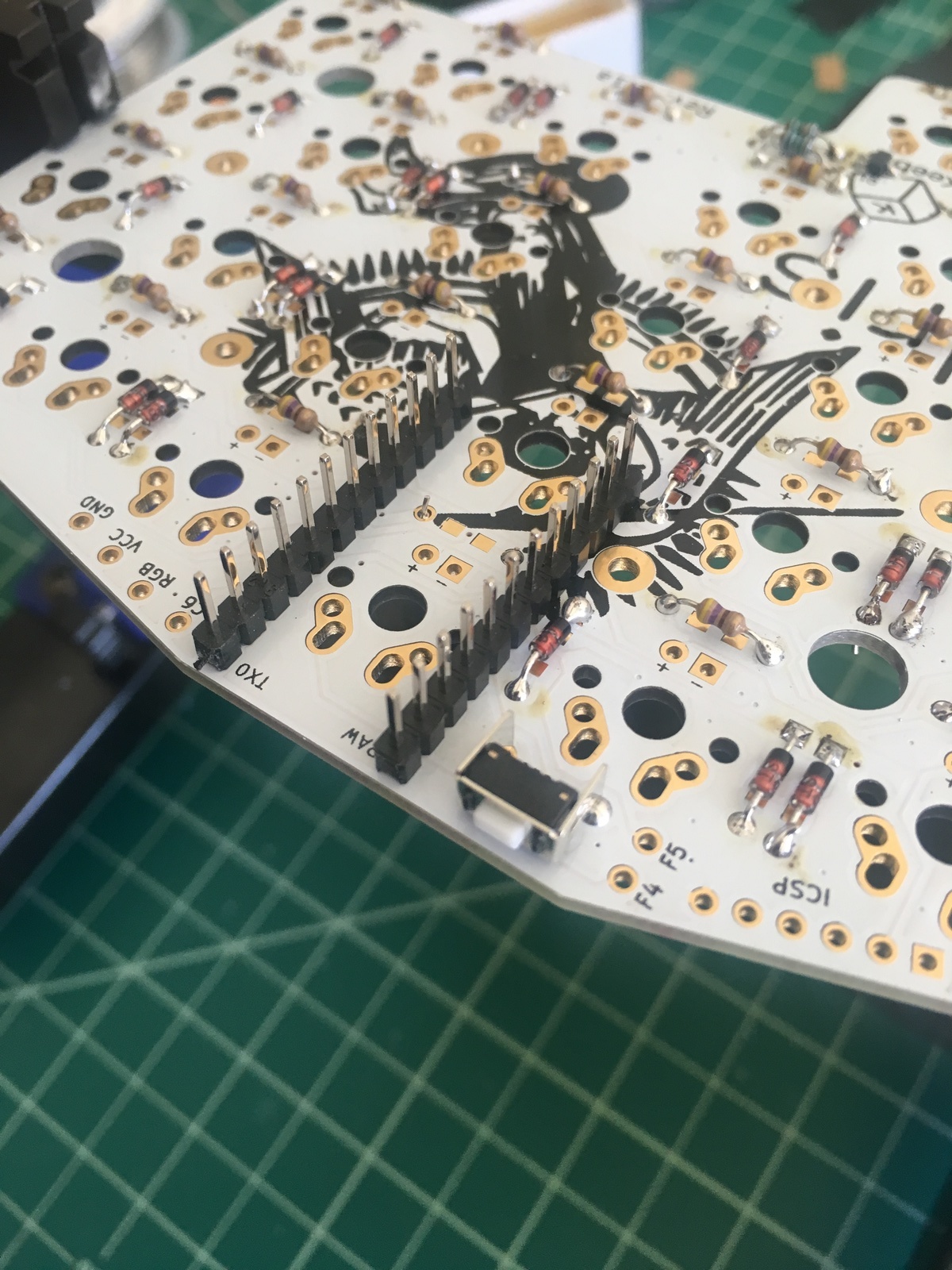
Next up I mounted the Pro Micro header pins:
I read in the guide that you should flash the controllers first just in case they’re faulty so I went inside to do that. Of course in doing so I got a migraine… I took some Ibuprofen, slept for a few hours, and thankfully it passed rather quickly.
So, I flashed the Pro Micros which was pretty easy having flashed my Atreus62 before and headed back to the garage.
I started lining up the switches and hot gluing them into place. Given that the Kailh box switches are plate mounted and the LEDs actually sit inside of them, I didn’t trust two solder joints to keep the switches in place when replacing keycaps. So, I decided to hot glue each switch on the underside of the plate. The drawback to this was having to line everything up more precisely:
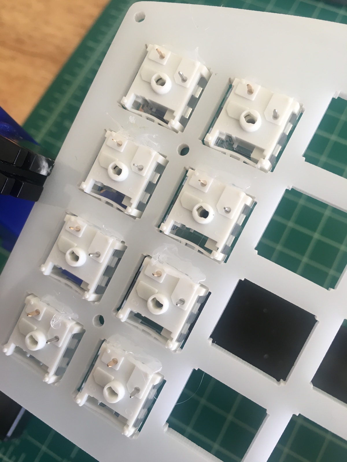
So, with the switches all glued in place, I put the LEDs on the PCB and carefully lined up the switches so that they would sit on top of the LEDs:

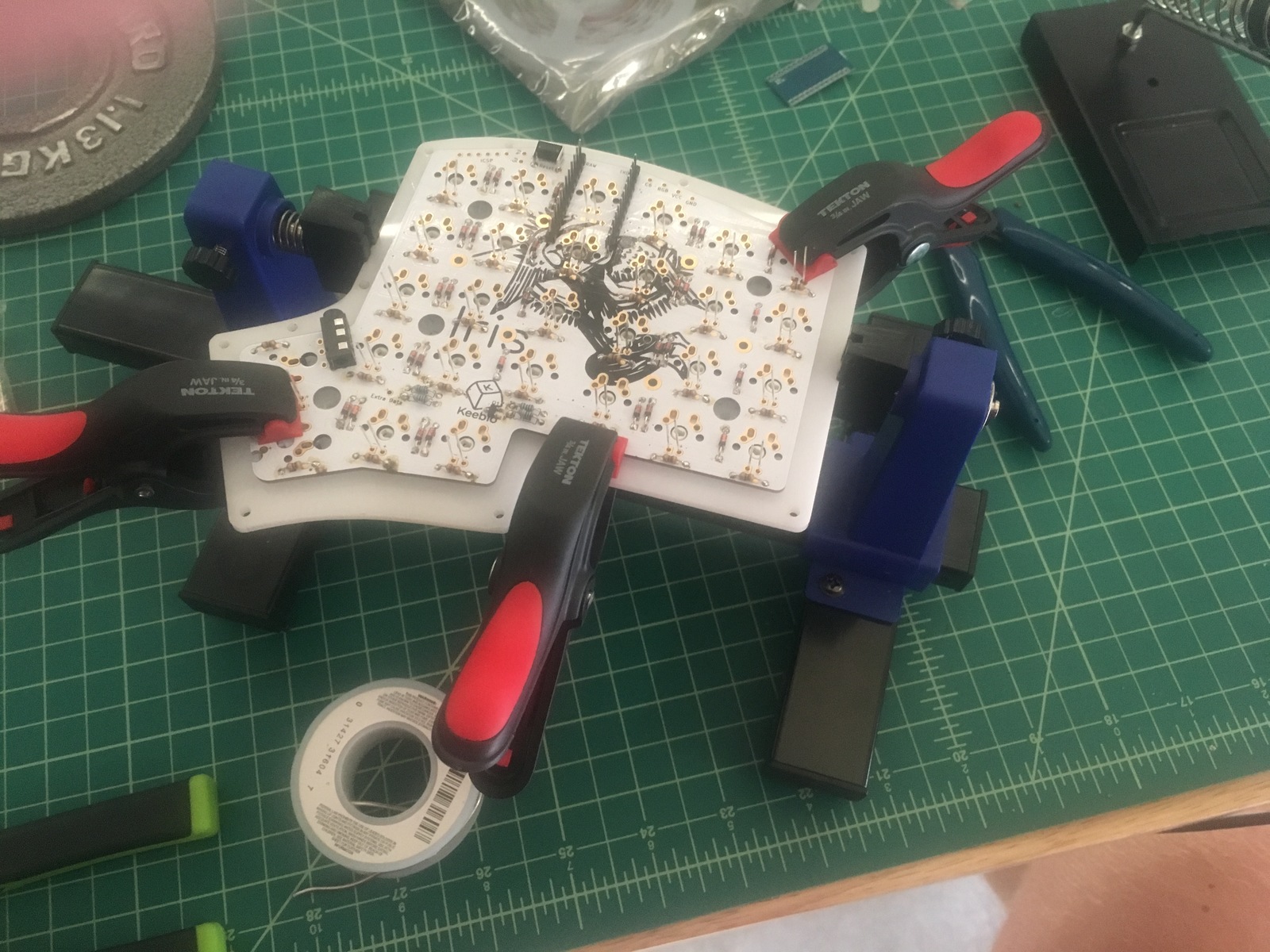
Finally, I clamped everything down to ensure it stayed lined up and as compact as possible while I started soldering:
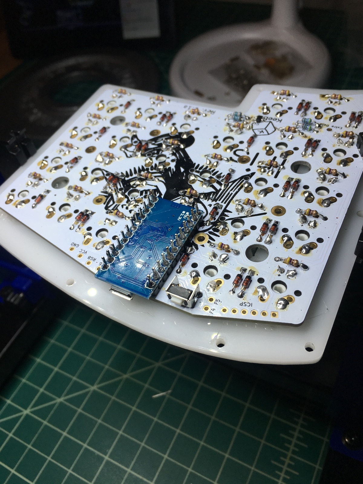
Next, I soldered the first Pro Micro. This was the easy one because I didn’t remove the plastic spacers from the header pins. It didn’t seem necessary because the USB port was already flush with the board:
The other Pro Micro was actually a giant pain in the ass. I did remove the plastic spacers from the header pins this time which was not fun and bent the pins out of shape. After readjusting the pins so the controller would fit, I came across another problem. When I soldered the pins, the solder at the bottom of the pin on the PCB would actually melt and the pin would come loose. For several of the pins I had to add some soler to the tip of my iron and then hold the pin with tweezers while soldering. It did work but this was probably the worst part of the whole build:
Lastly, I added the RGB strip for underglow:
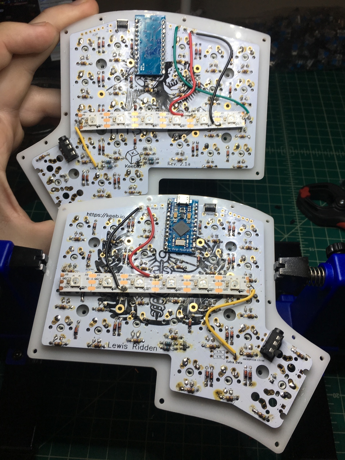
This part was pretty simple which was refreshing after the controller shenanigans. I employed a similar technique I used for the MOSFET component where I would tin the pads on the RGB strip with solder. Then all I had to do was bring the tip of the wire to the pad and heat it up.
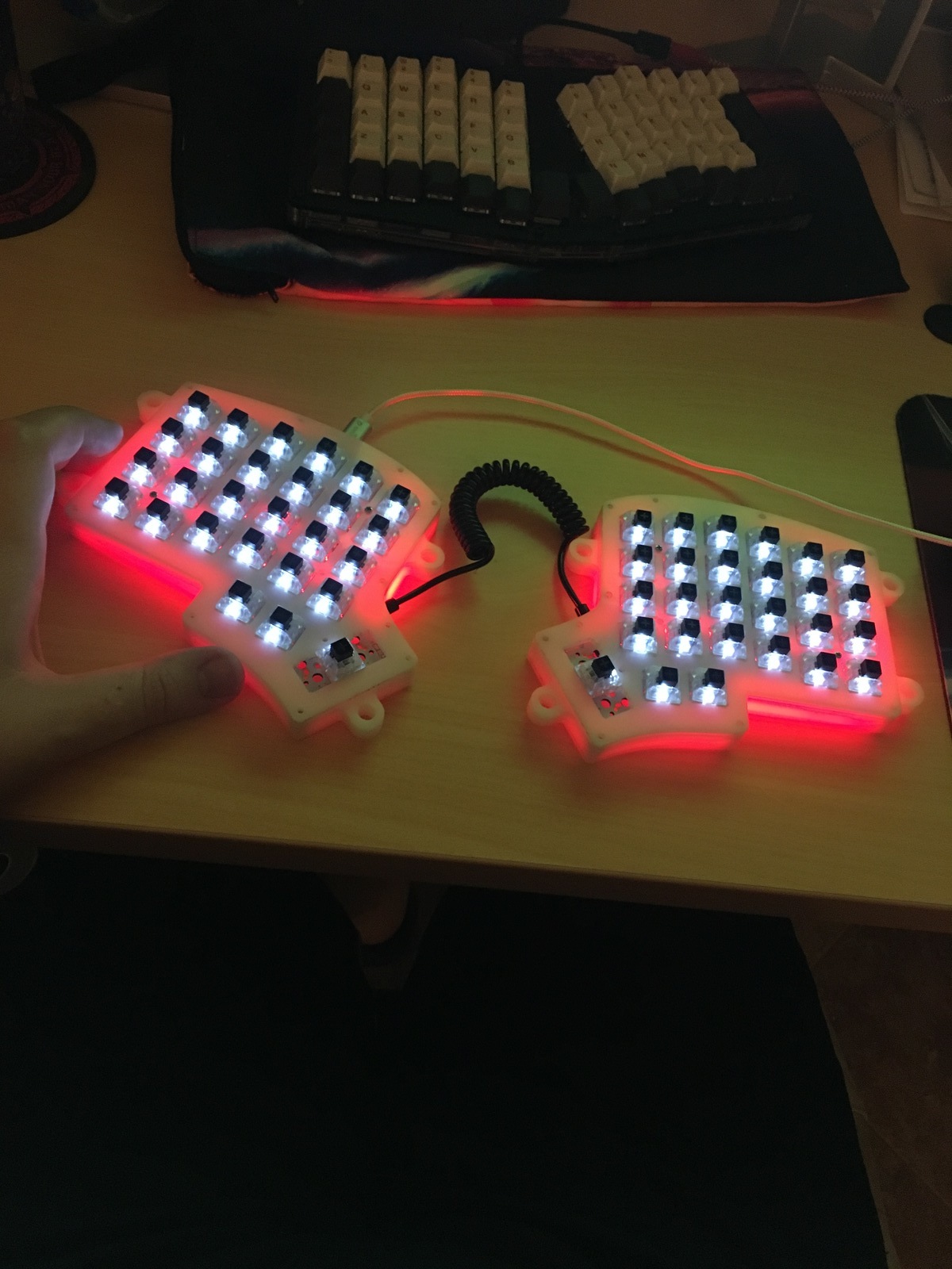
And the best part of the whole thing was plugging it in and having it just work!