First Handwired Speedo
This build log documents the process I went through in creating the first, functional Speedo keyboard. It is rather long so a table of contents is provided to make finding a specific step a bit easier.
Table of Contents
- 2018/02/16
- Creating the Thumb Clusters
- 2018/02/23
- Rev1 Comes to an End
- Oops
- Solution
- Next Steps
- 2018/02/25
- Order is in for Rev2
- 2018/02/26
- Deciding on Parts
- The Decision
- A Close Second
- Deciding on Parts
- 2018/03/07
- The parts arrived!
- 2018/03/10
- Starting the Build
- Inserting the Switches
- Gluing the Switches in Place
- Soldering the Diodes
- Starting the Build
- 2018/03/11
- Rows and Columns
- Rows
- Columns
- Rows and Columns
- 2018/03/13
- Rows and Columns (Cont.)
- More Columns
- Rows and Columns (Cont.)
- 2018/03/14
- Rows and Columns (Cont. x 2)
- Finishing the Columns
- Rows and Columns (Cont. x 2)
- 2018/03/28
- Destroying a Teensy 3.2
- The First Few Columns
- The Accident
- Destroying a Teensy 3.2
- 2018/04/02
- Getting the Controller Ready
- Attaching the Wires
- Placing the Controller
- Getting the Controller Ready
- 2018/04/03
- Finishing Up the Soldering
- Connecting the Rows
- Connecting the Columns
- Keycaps and Firmware
- Finishing Up the Soldering
02/16/2018
Creating the Thumb Clusters
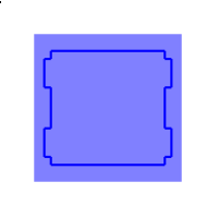
I started off by copying a single switch cutout and rotating it back 10 degrees so it would be horizontal:

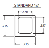
I wanted to visualize what the keycaps would look like to get a better idea of how to position the keys. PimpMyKeyboard provides PDF spec sheets for their keycaps so I got the dimensions for a DCS 1u keycap from that and rounded to 18.1mm:
Using those dimensions, I added the keycap overlay:
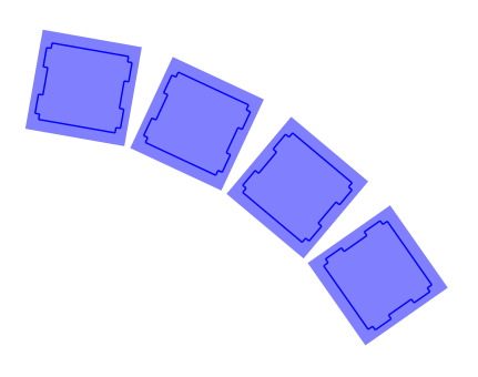
I figured the best way to get a nice arc shape for the thumb keys was to lay them out on a circle. I had to brush up on some trigonometry to remember how to get the coordinates of points on a circle:
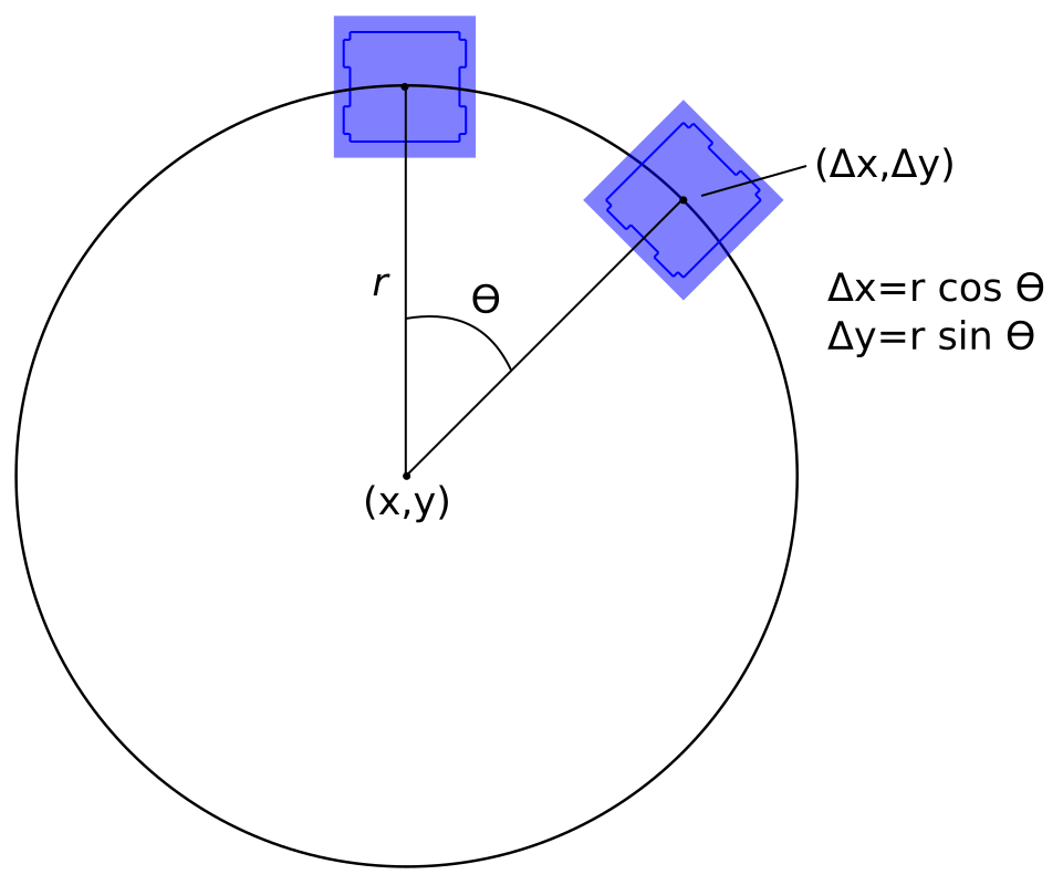
One slight annoyance in Inkscape (Or SVG files in general?) is that the X,Y coordinates of an object are not based on the object’s center but on the bottom left most point:
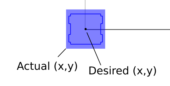
Also, when an object is rotated, height and width changes as well:
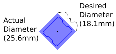
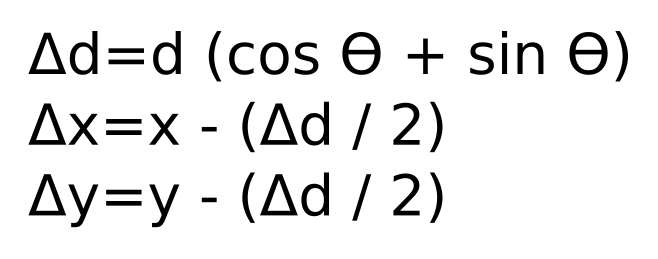
These aren’t a big deal we can easily get the adjusted values with a few simple equations:
The last step was finding a suitable value for r. I could have done some more math and come up with a radius based on the distance between the closest corners of each keycap; however, that seemed like more work than doing a little bit of trial and error.
So, I started with a radius of 50mm. That was too small so I bumped it up to 100mm, which was too big. From there I basically just did a manual binary search until I came to the value of 82 which seemed to suffice.
I decided to start at an angle of 10 degrees – which is the angle the keys are already at on the Atreus62 – and bump it up by 15 degrees for each additional key.
The final product:
After that I just had to paste the thumb clust back on the original board. I lined up the first key using the same spacing that the existing keys on the board used and then redesigned the bottom of the case to accomodate the additional real estate.
I ordered the first revision from Ponoko so I will see if it is comfortable and if I think anything should be changed.
The first revision:
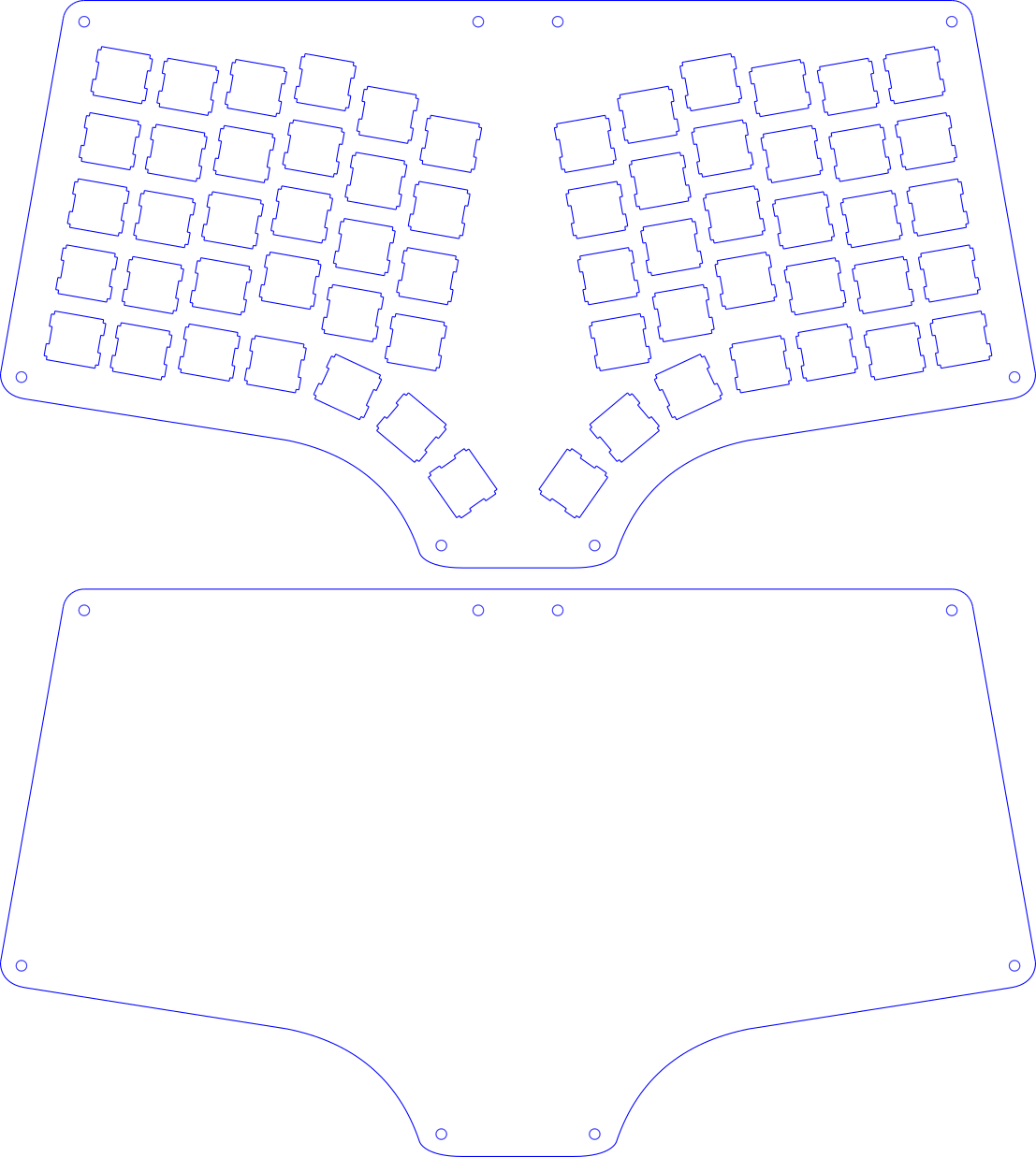
02/23/2018
Rev1 Comes to an End
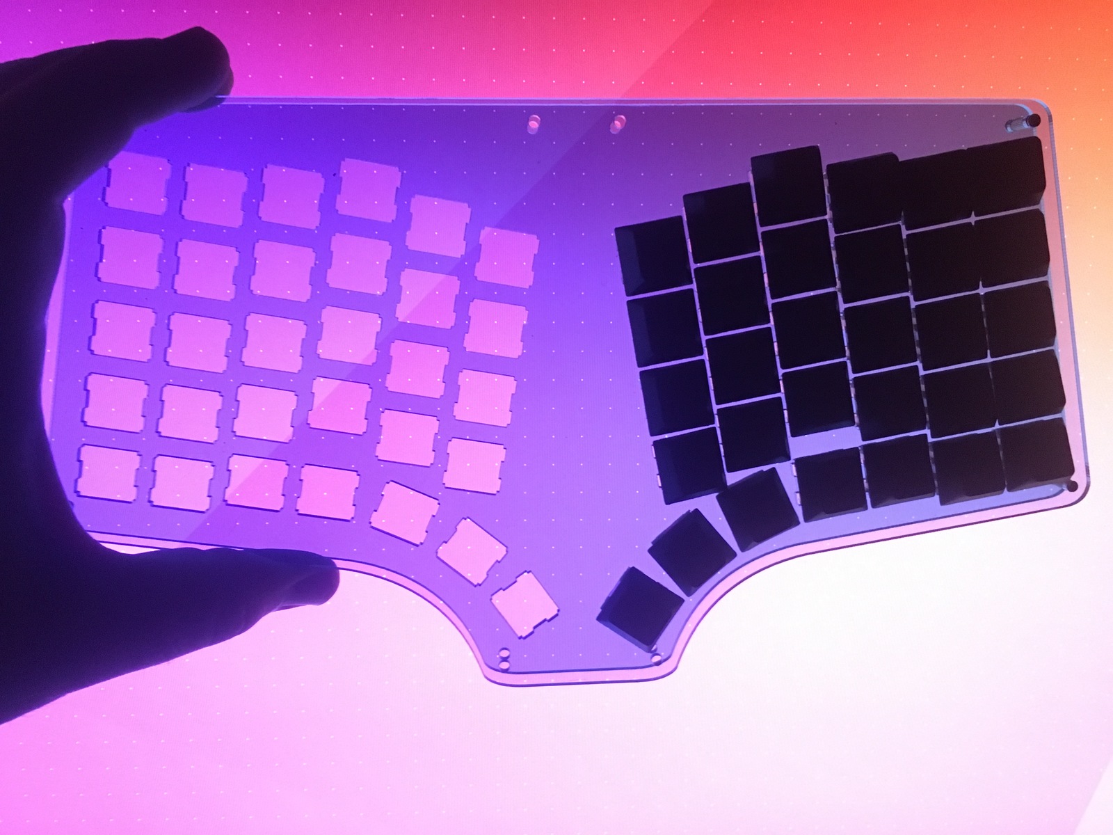
Yesterday the first iteration of the case files came from Ponoko. I’m glad I chose Ponoko because it was the cheapest option and I made a couple of mistakes.
They were out of the material that I ordered which was a light blue matte acrylic so they used the clear blue gloss acrylic instead. Some pictures of the plates:
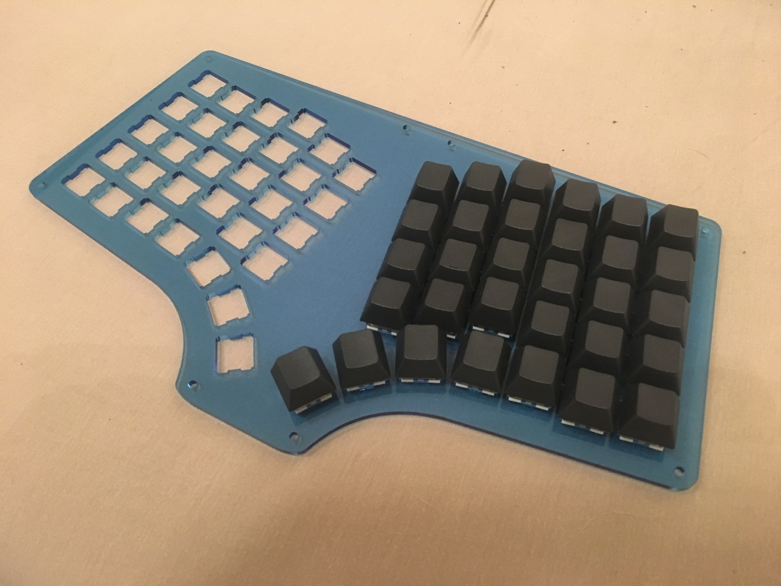
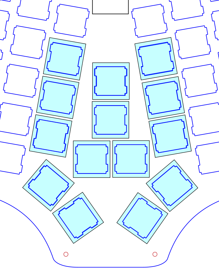
Oops
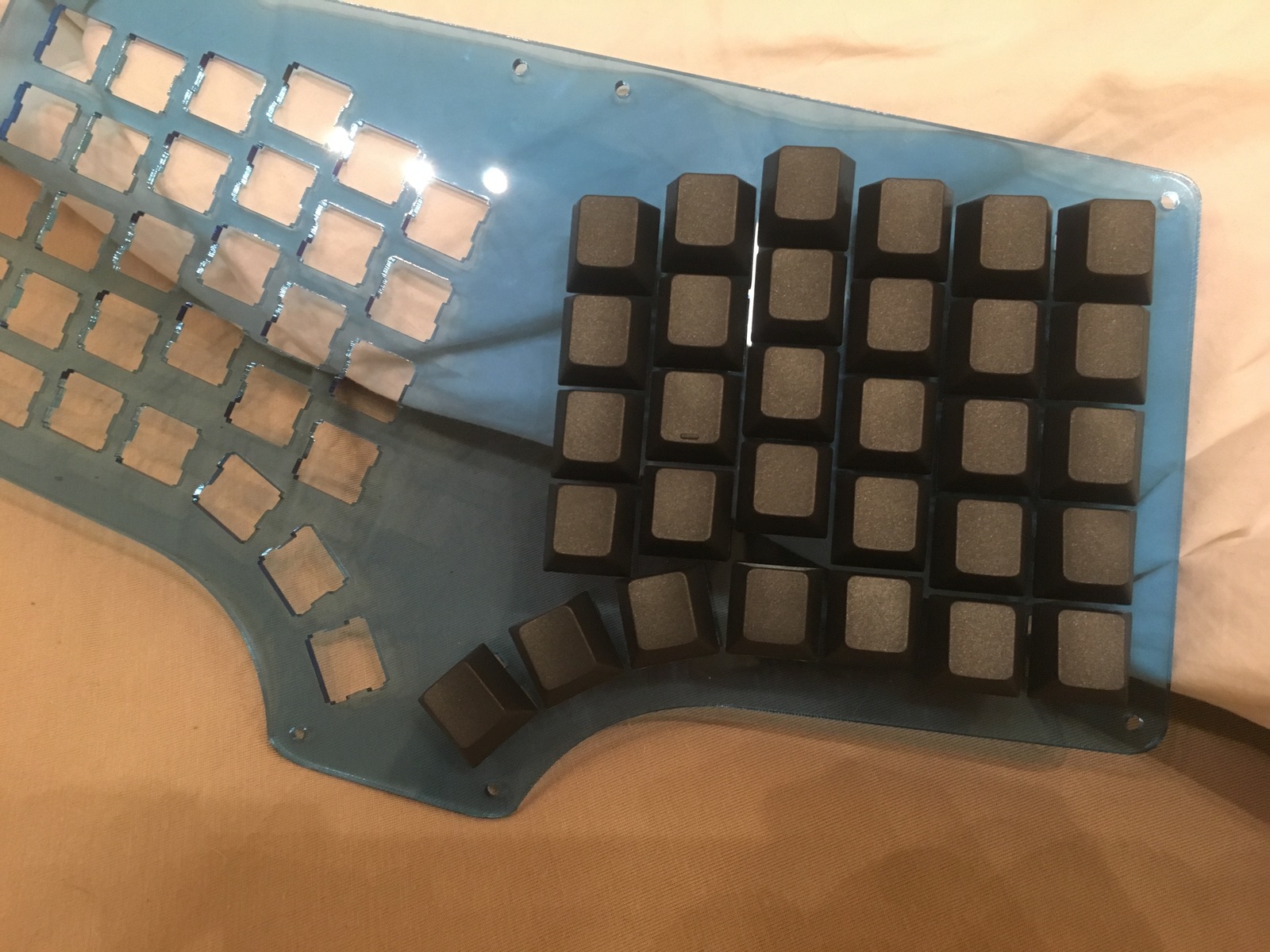
The critical mistake that I made is the the second innermost thumb key is too close to the key just above it. I thought I left enough space for the keycaps to fit but I guess not.
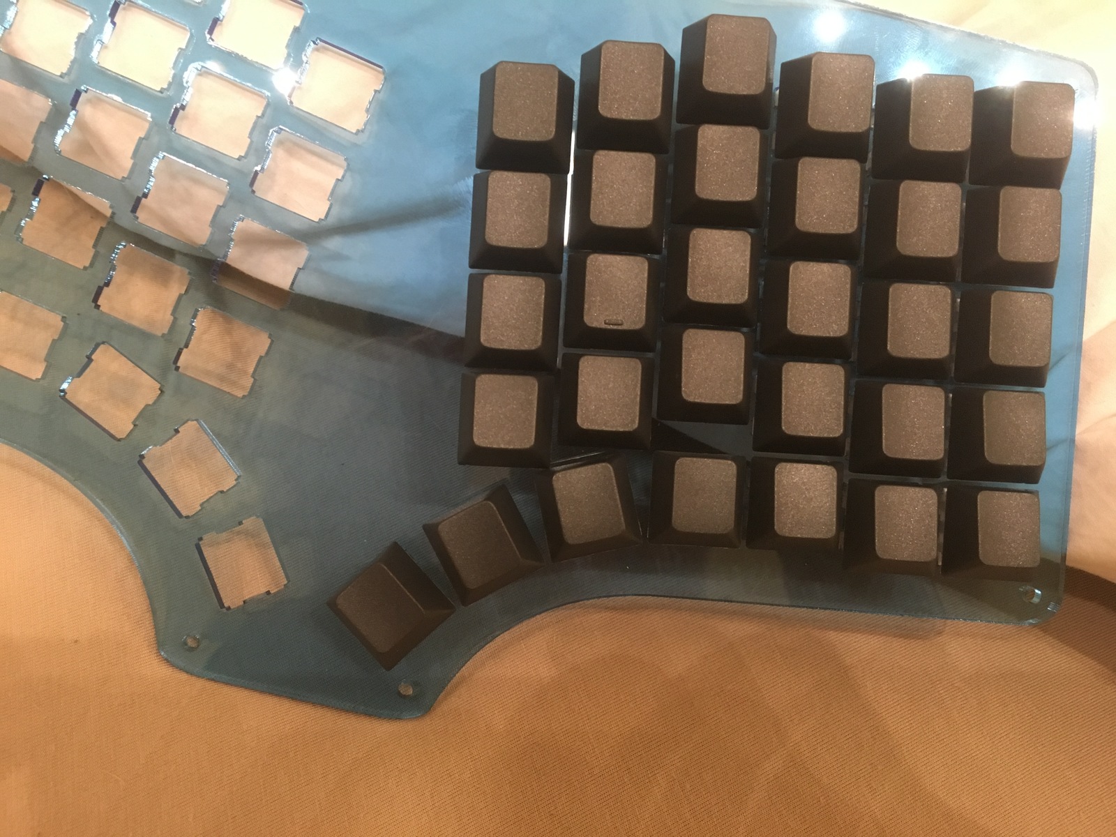
It’s more obvious in this picture I took in front of my monitor:
Solution
Anyways, after a bit of comparing the Atreus62 keys to the Speedo, I’ve decided to put the two innermost thumb keys back to their original location. Pulling the innermost key further down is actually less comfortable and the angle on the second innermost thumb key is unnecessary.
That said, the two outer thumb keys are incredibly comfortable so I will be leaving those exactly as is. That’s actually a bit of a relief because the perimeter of the case doesn’t have to change now.
Next Steps
So, the next step will be moving those two thumb keys back and then designing the middle layers. I’m thinking I might make two different middle layers:
- A “top” middle layer with an area for the controller to sit
- A “bottom” middle layer that only runs the perimeter of the case
Since I don’t have a PCB, the controller is just going to be hot glued to the case. Adding a plastic area for it to fit snuggly in should help avoid any issues when plugging/unplugging the USB cable. The downside is that a translucent switch plate is out of the question because the hot glue will be ugly to look at.
The alternative is to use a breakout board, something like this:
https://www.tindie.com/products/loglow/teensy-32-breakout-revision-d/
Unfortunately that is big and a goal for this board is to keep it as low profile as possible.
I’m hoping to get rev2 done tomorrow and ordered by Monday! I currently have a Kailh low profile switch tester and 70 low profile keycaps in the mail. I’m hoping to decide which switch I plan to use so I can get the rest of the parts I need ordered ASAP.
02/25/2018
Order is in for Rev2
So this evening I finally got around to making the adjustments that I wanted in revision 2.
I actually decided on one more significant change which was to add 4 additional keys in the center of the board to reduce the wasted space. I plan to use these as media keys (Volume up/down, play/pause, and next track) but I could see how some folks might like having dedicated arrow keys. They also provide a decent spot to showcase artisans for those who are into that sort of thing.
This time I did a better job at using keycap overlays to ensure that all of the keys would fit:
I took that screenshot before I fixed the alignment so the final version is actually centered correctly.
Other than that, none of the changes are all that interesting so I’m not going to go into the process here. The changes included:
- Move the two inner thumb keys back to their original spots
- Add more screwholes to the board to make it feel less flimsy
- Change the screwholes to fit M2 better because I have a lot of extra M2 screws and standoffs lying around from Iris builds
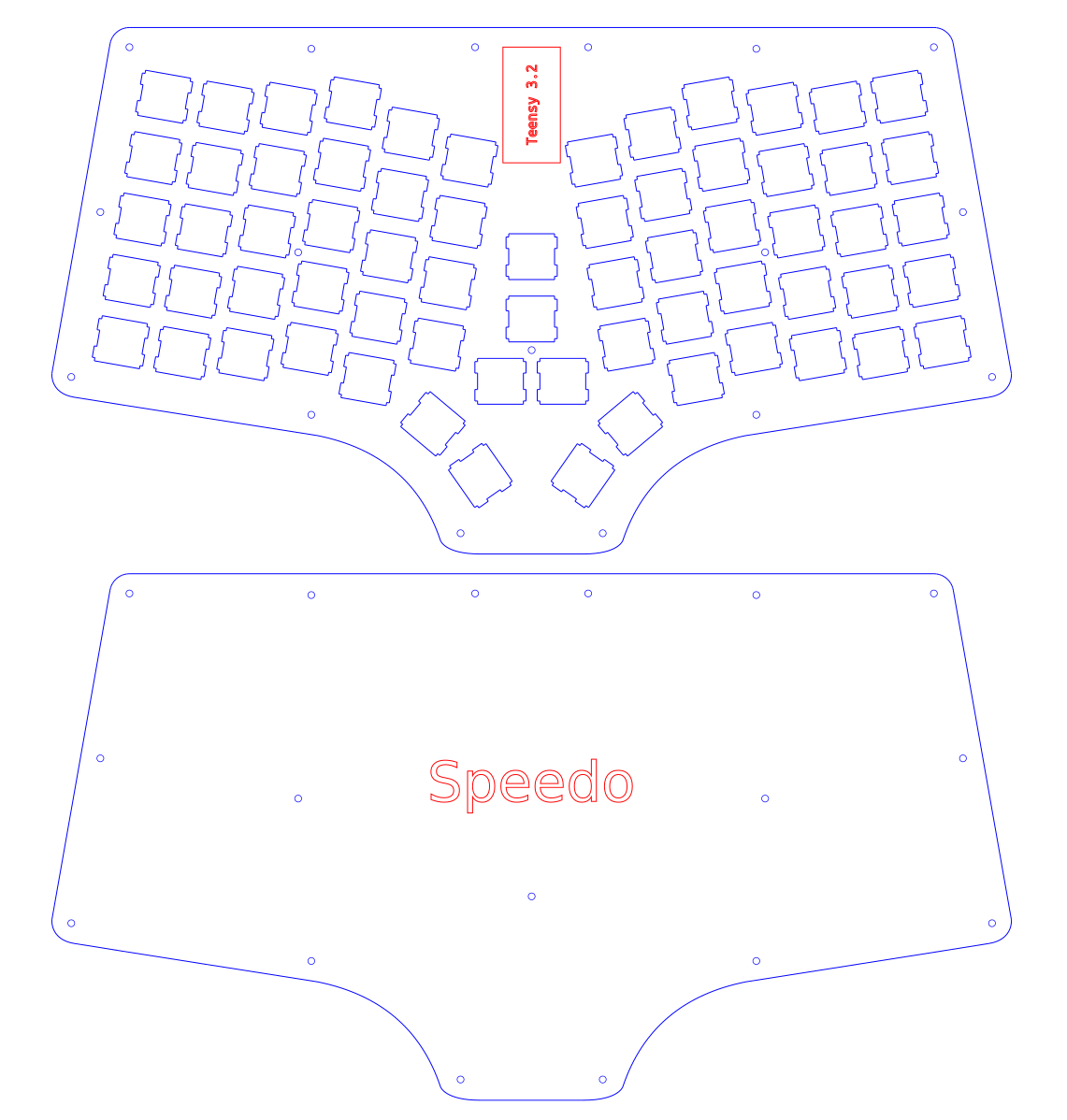
- Add etching around where the Teensy should sit
- Add Speedo logo etching on the back
The final product:
I’m hoping that this one feels good enough to settle on. Ideally I will use this opportunity to learn a little more about PCB design and try to design a PCB once I’m happy with the layout.
02/27/2018
Deciding on Parts
Now that the second revision of the case file has been ordered from Ponoko, I need to decide what parts I’m going to use for the first build.
The Decision
- Switches: Kailh low-profile reds
- Keycaps: Blank low-profile white keycaps
I bought a low-profile switch tester set from NovelKeys and tried out all of the switches. In terms of feel, the jades actually feel heavenly but they are also incredibly loud and I would feel guilty using them in the presence of others.
These days I generally like linear switches but the low-profile mixed with linear actually doesn’t feel great. I would go with browns instead but they are out of stock on NovelKeys so it looks like I’ll just suck it up and use reds.
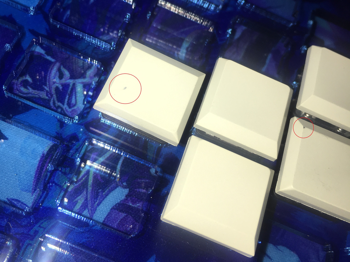
One shitty thing about going with low-profile switches is that only one store sells compatible keycaps and the quality leaves much to be desired. I ordered 70 of them and many of them have blemishes as shown in this picture:
A Close Second
There is currently a group buy in progress for some keycaps that look really nice. The base kit is £61.50 which is $85.81 at the time of writing this. It has the exact amount of 1u keys necessary to fill the keyboard and would look like:
Link: http://www.mechsupply.co.uk/product/devlin-q-series-pennine-planck-preonic-ergodox-keyset
I’ve heard very good things about all of the Devlin keycaps which is what is what tempted me the most to go this route. I also already have plenty of normal switches so I wouldn’t need to order any.
I’ll probably end up getting these keycaps anyways and using them in a future build.
03/07/2018
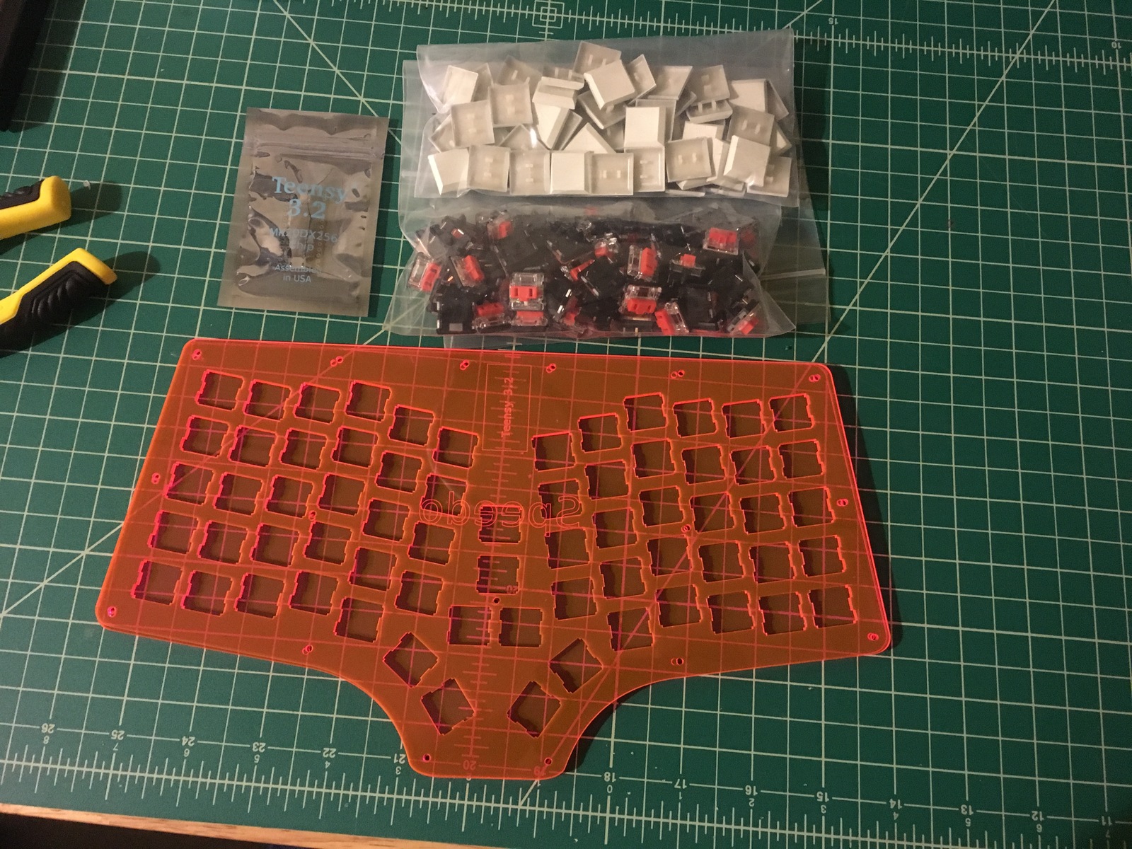
The parts arrived!
My low-profile keycaps and Kailh choc red switches arrived so I should now have everything I need to get started on the build.
03/10/2018
Starting the Build
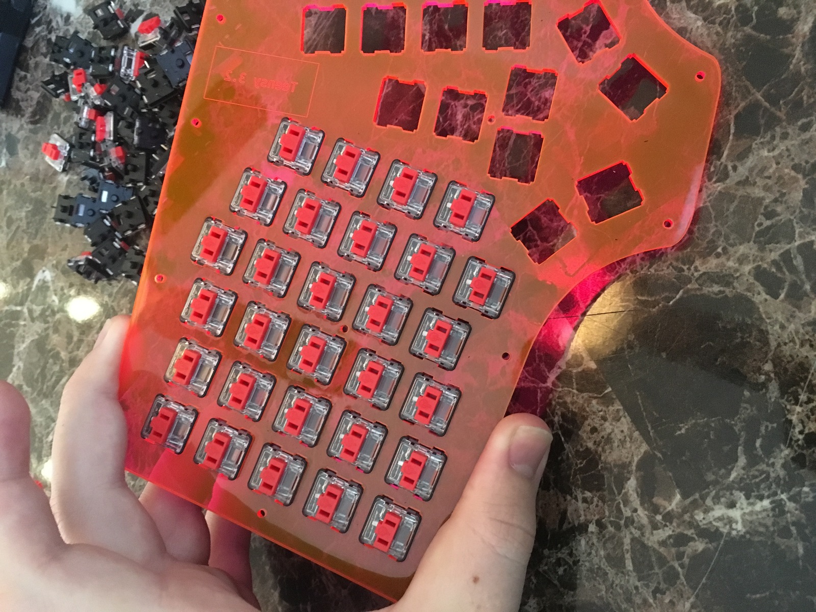
Inserting the Switches
First step was putting the switches into the plate:

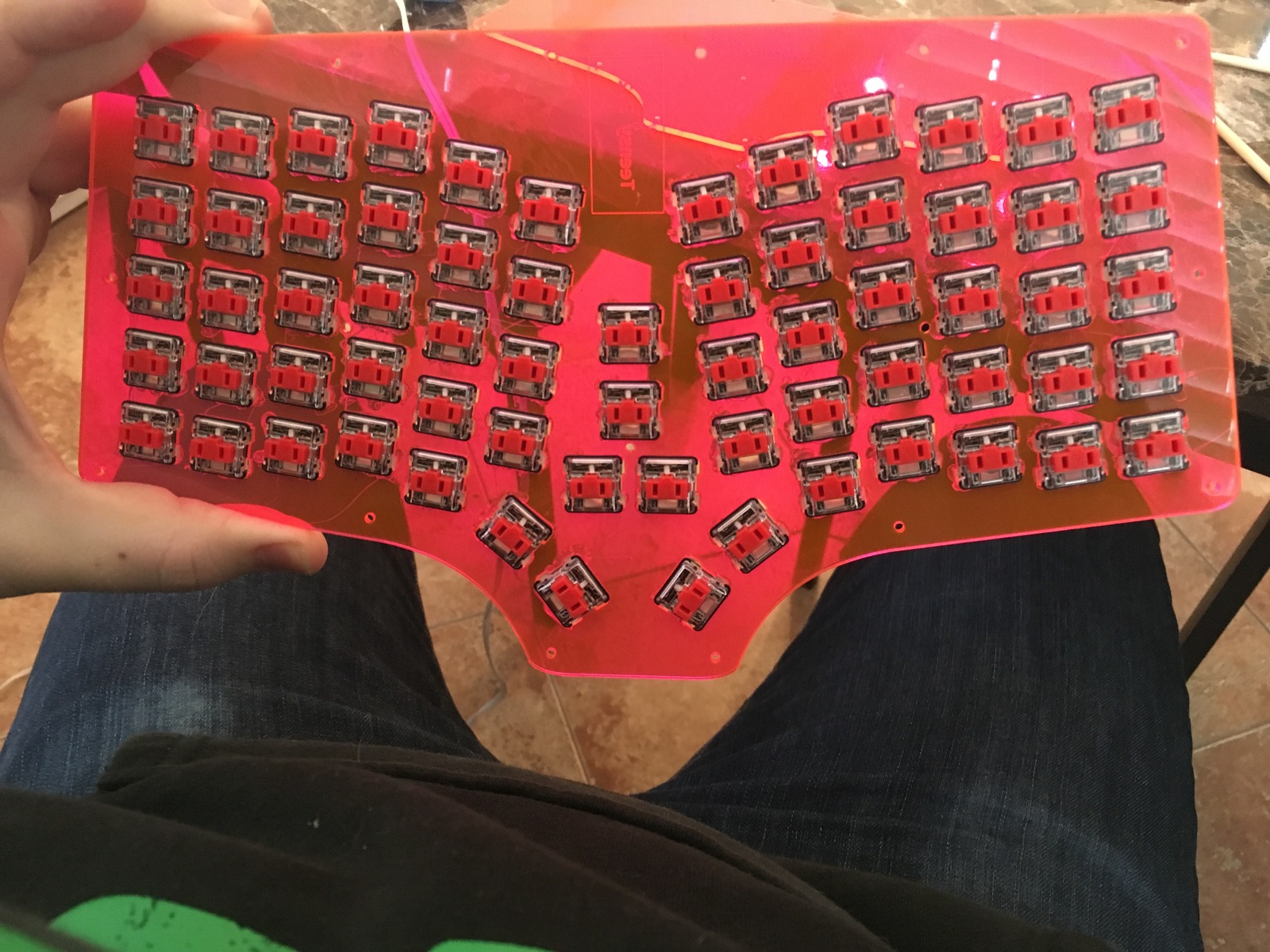
Gluing the Switches in Place
Next was to hot glue the switches in place. Because the switches wouldn’t be PCB mounted, this is necessary to keep them aligned and in place:

Soldering the Diodes
For the soldering process, I roughly followed the advice from this guide on GeekHack:
So, first thing I did was create little loops in each diode and place them on the switch pins.
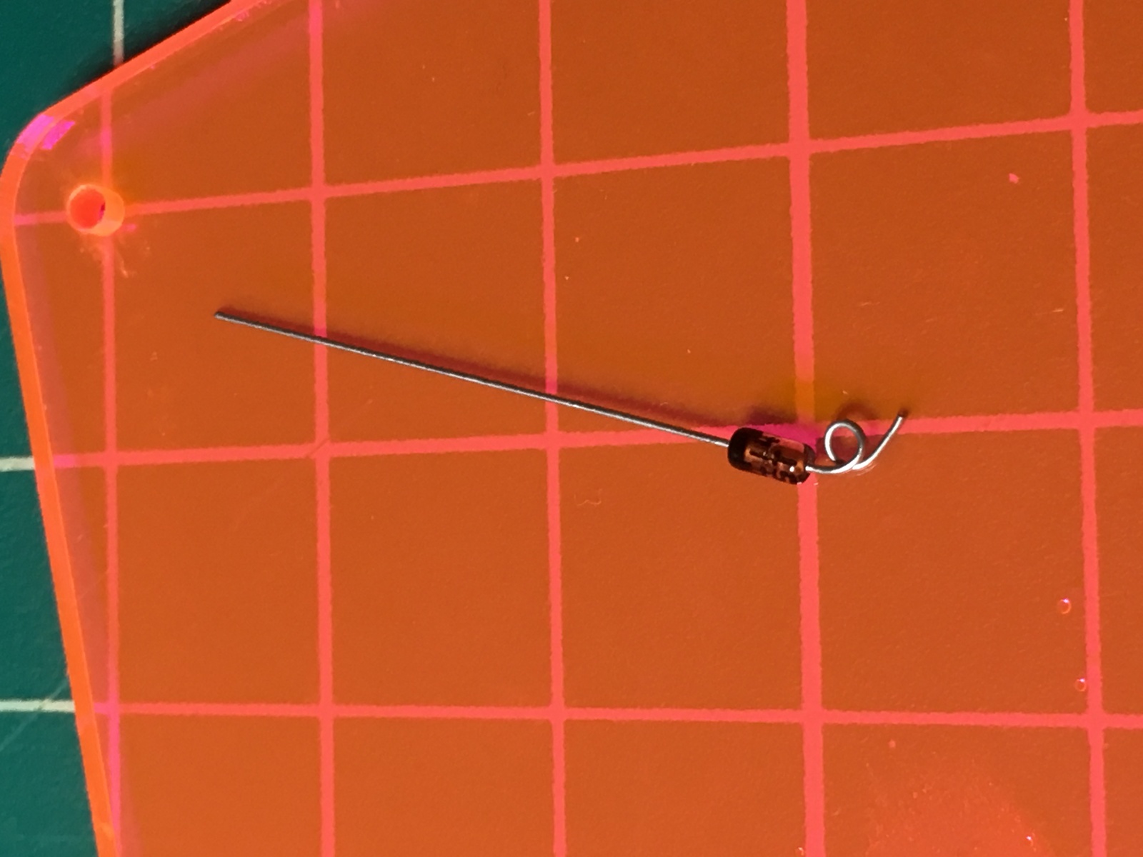
And then I soldered them.
I ended the day with all of the diodes soldered but didn’t want to get started on the rows yet.
03/11/2018
Rows and Columns
Rows
With all the diodes done, I started on the rows. I roughly measured the distance between switches and then stripped the wire in segments.
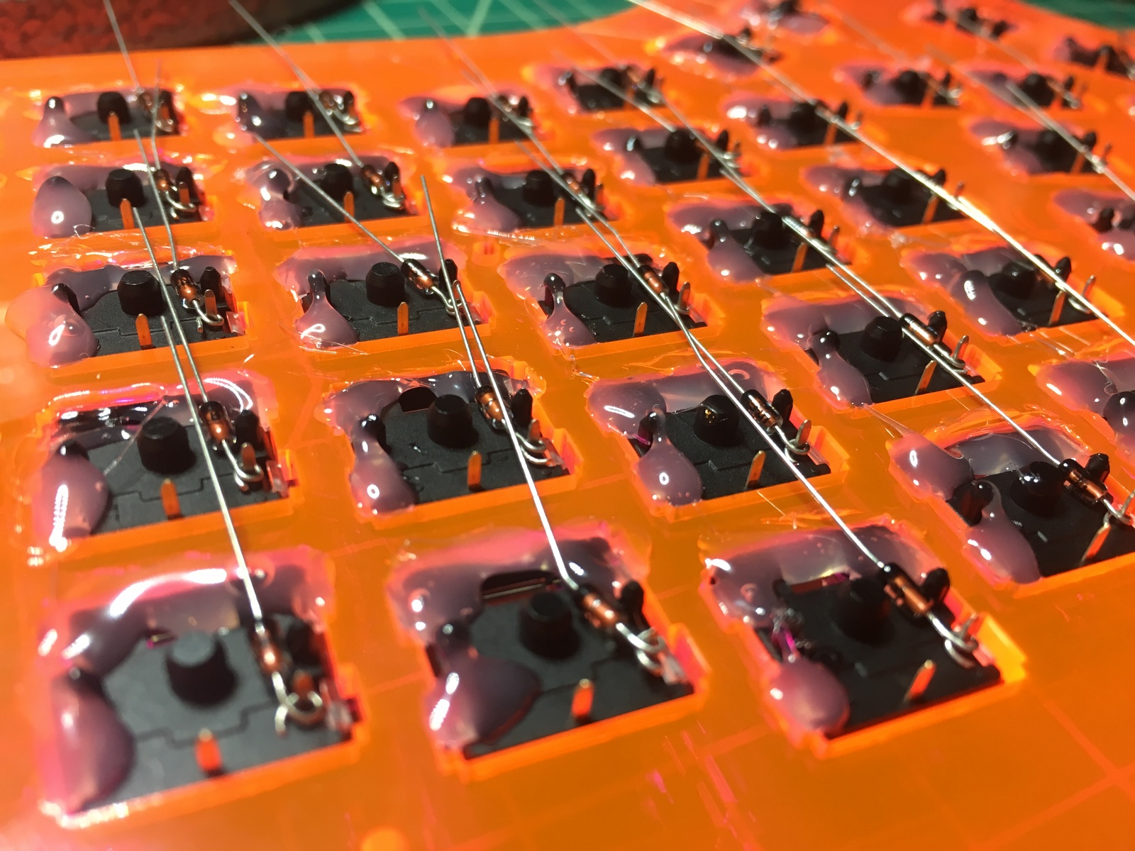
Then, following the advice in the guide, I looped each diode pin around the stripped section of wire and soldered the joint.
Rinse repeat:
And again…
Ah, finally.
Columns
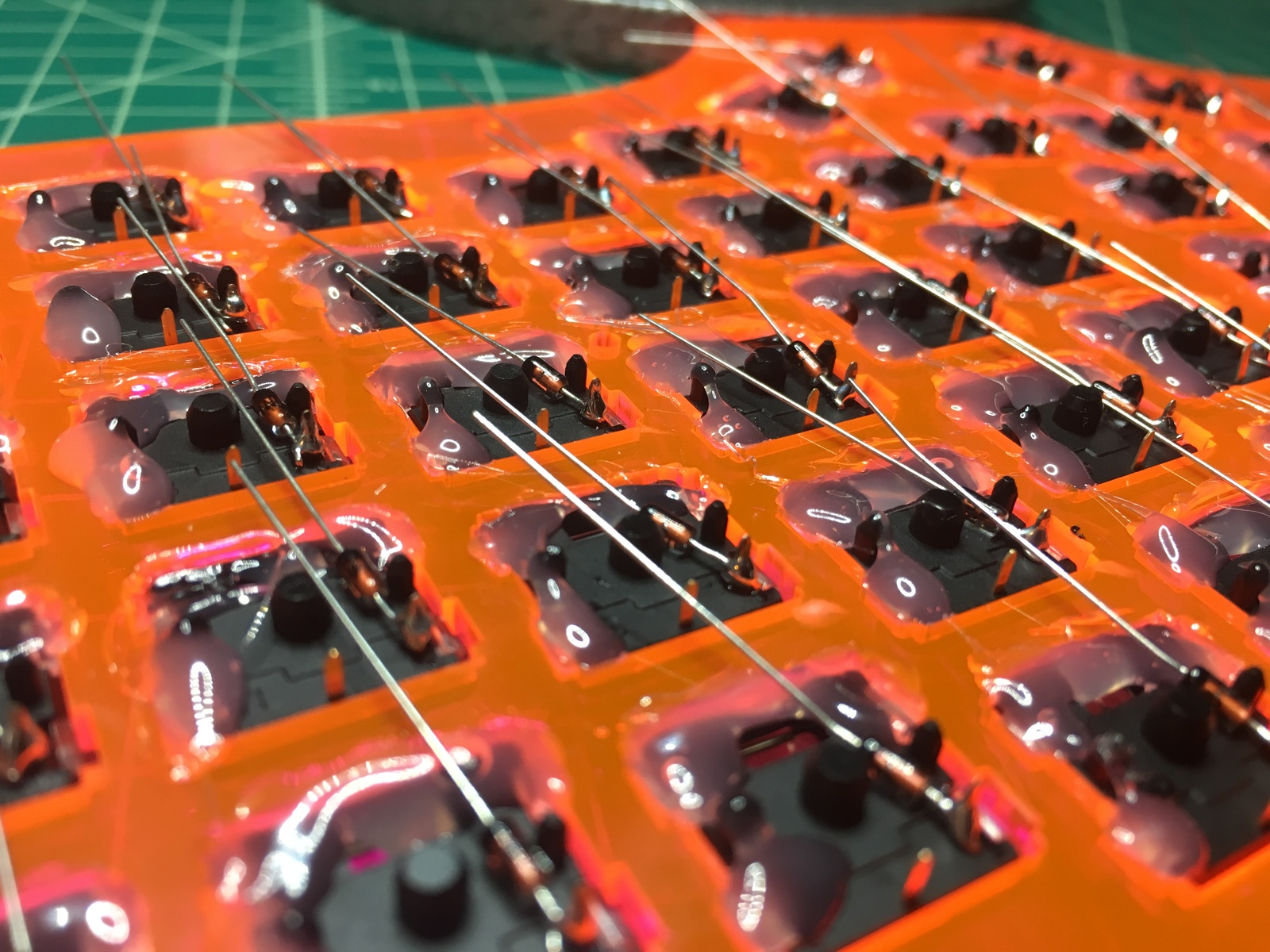
With the rows done, I started on the columns. Again, I roughly measured the distance between the switches vertically and then stripped them accordingly.
I created the first loop on one end and soldered that to the top switch in the column. Then, I would move the sleeve close to the joint, wrap a new loop around the pin on the next switch and solder that joint. Repeat this a few more times and the column is done.
I only made it through 3 columns before deciding to call it a day. Making the loops for both the rows and columns is an ultra-tedious pain in the ass.
03/13/2018
Rows and Columns (Cont.)
More Columns
Not much to say other than that I continued on the columns. As previously mentioned, they are quite annoying to do so I decided to stop after 6.
For the most part I enjoy the building process but this particular task was definitely a test of my patience.
03/14/2018
Rows and Columns (Cont. x 2)
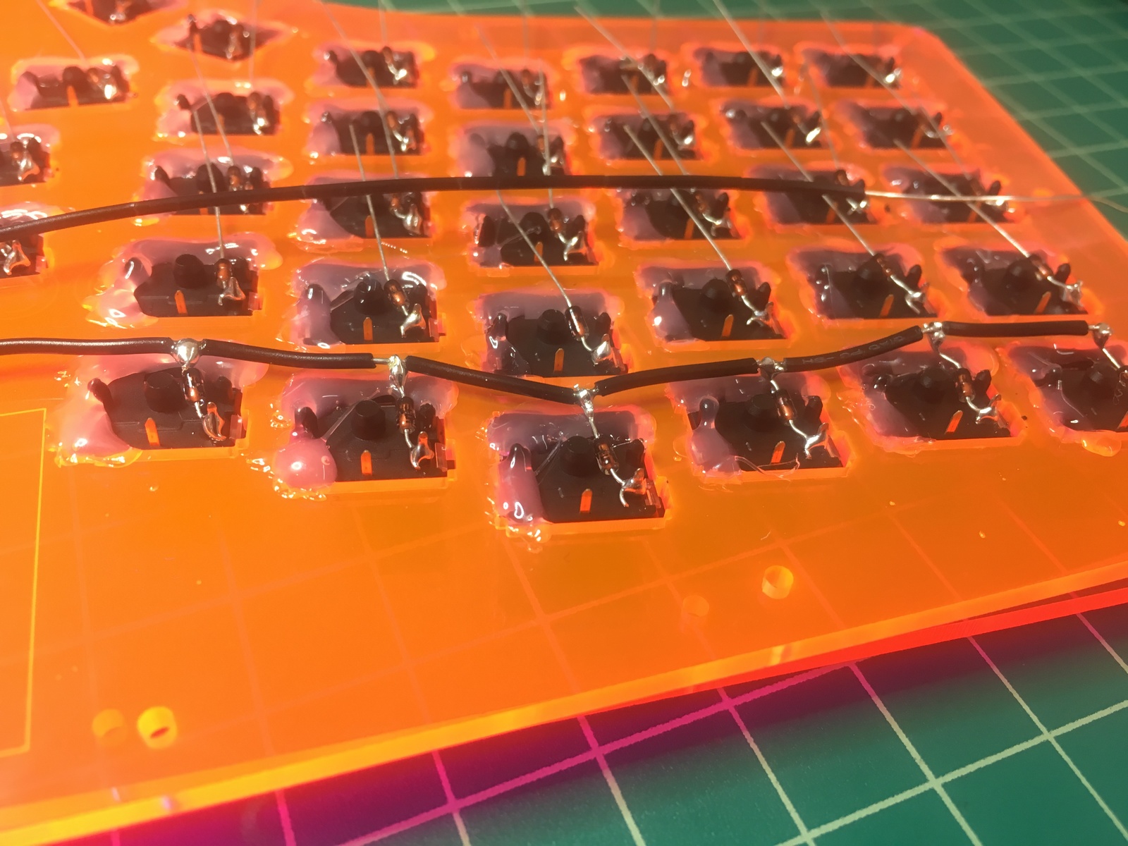
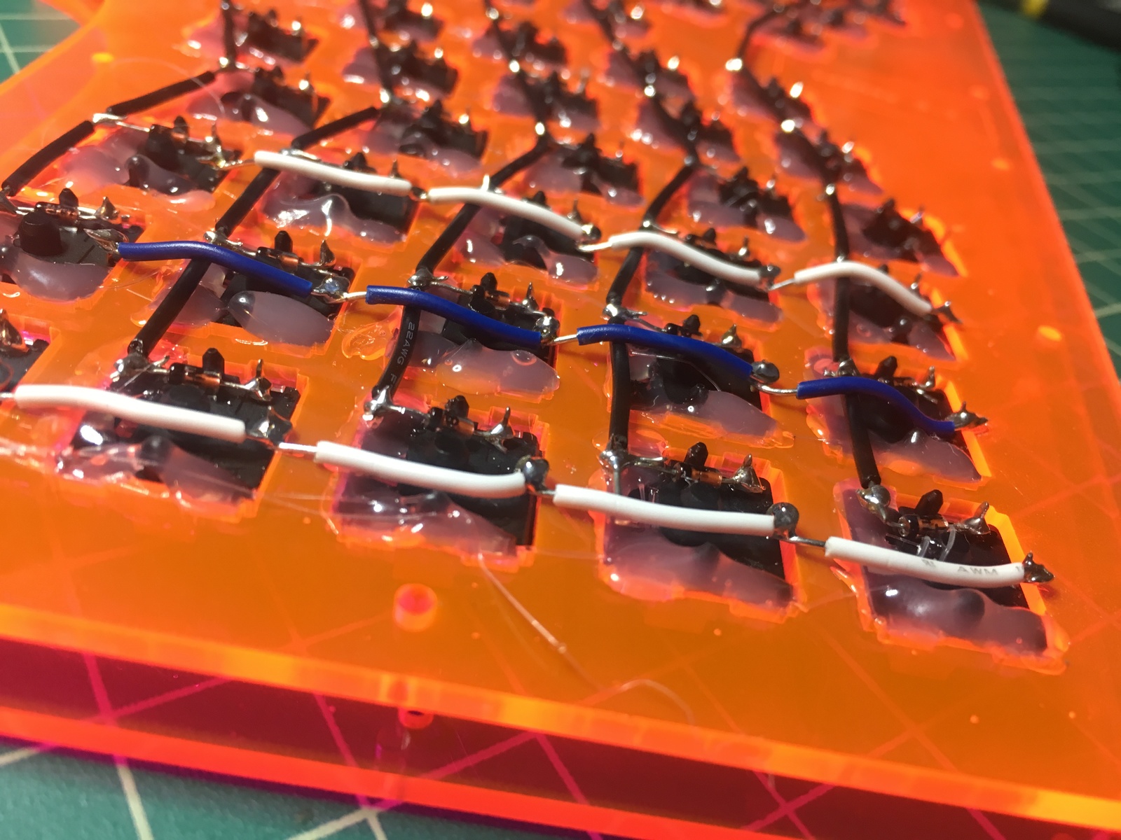
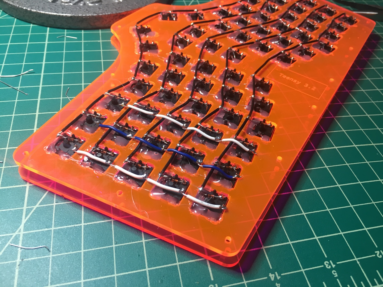
Finishing the Columns
I finished up the columns and decided on how I wanted to wire up the middle keys:

03/28/2018
Destroying a Teensy 3.2
The First Few Columns
The final step of attaching the controller was upon me so I started wiring up the columns. I was soldering them to the switches first and then to the PCB:
The Accident
I have something called benign essential tremor which causes my hands to be a bit shaky. Normally it isn’t problematic but today it was.
I couldn’t keep my hand steady enough and I accidentally got solder on the pins of the processing unit on my Teensy 3.2.

Trying to use a solder sucker to clean it up didn’t help and I ended up just spreading it around even more.
So, I scrapped the chip, desoldered the few switch joints I’d completed, and ordered a Teensy 2.0.
On the bright side, the Teensy 3.2 requires setting up ChibiOS to use QMK and there’s not much documentation for doing that. At least the 2.0 should make the firmware setup process easier.
04/02/2018
Getting the Controller Ready
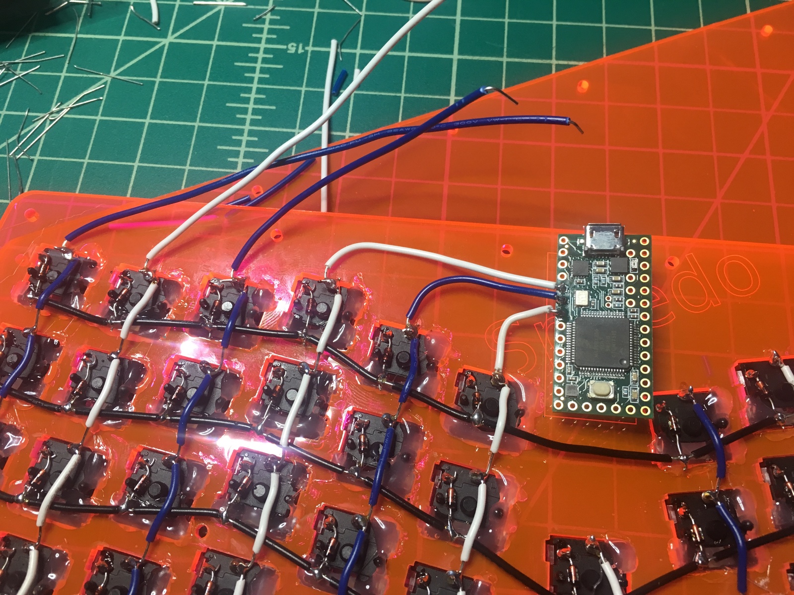
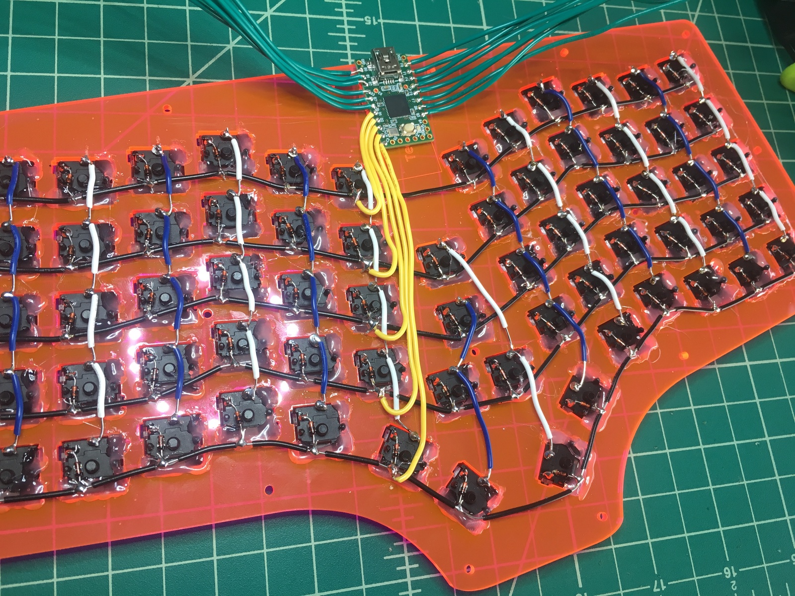
Attaching the Wires
To avoid making the same mistake again, I decided the attach the wires to the contoller first this time.
I cut wires plenty long to reach each row/column switch, stripped one end, looped it, and then solder to the backside of the controller.
I forgot to take pictures during this process, but this is the end result:
Soldering on the bottom side of the chip let me worry less about other electrical components in close proximity to the solder joints.
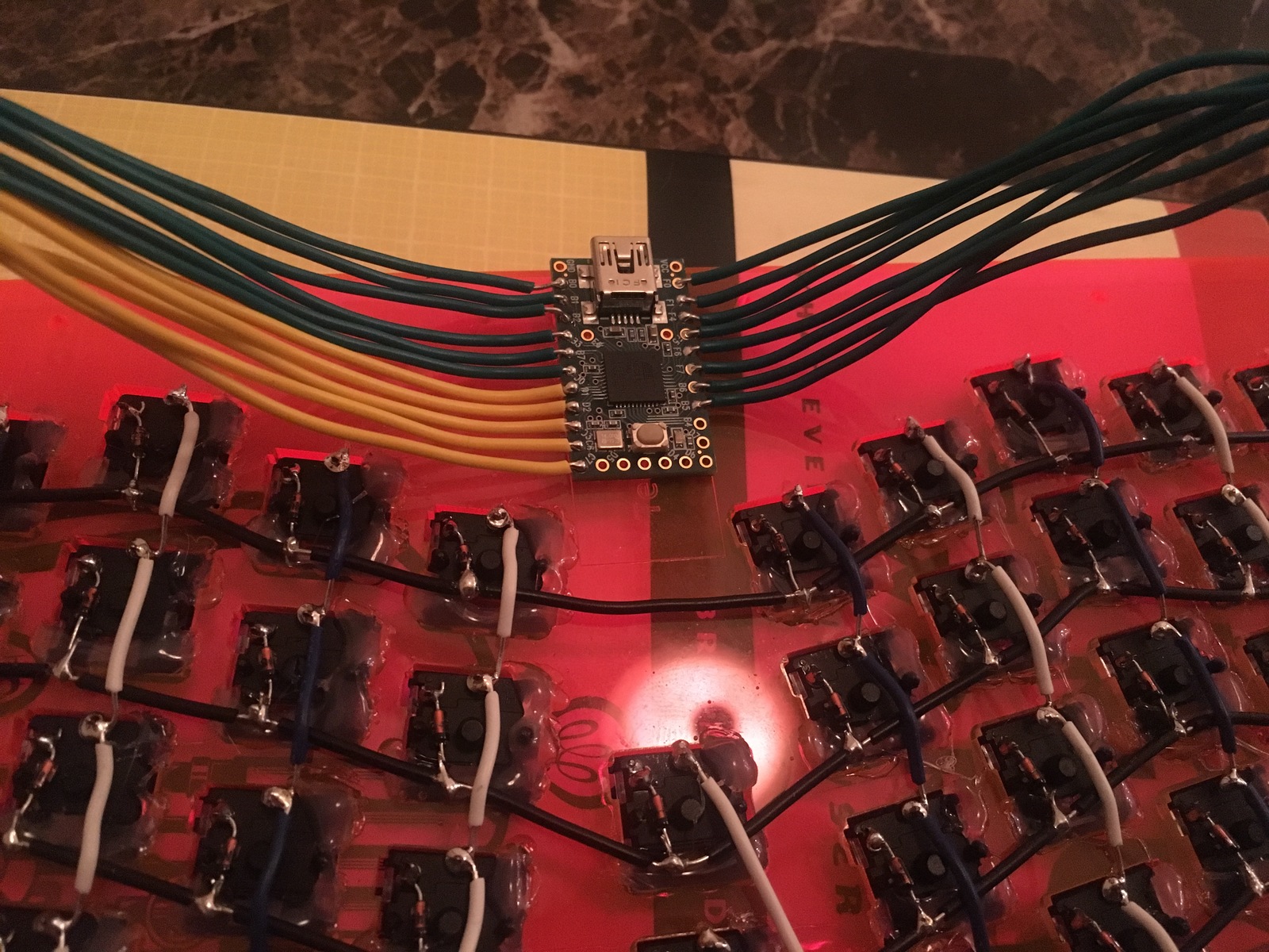
Placing the Controller
With all the wires attached, I used flush cutters to clean up the solder joints and then hot glued the chip to the plate to keep it in place.
04/03/2018
Finishing Up the Soldering
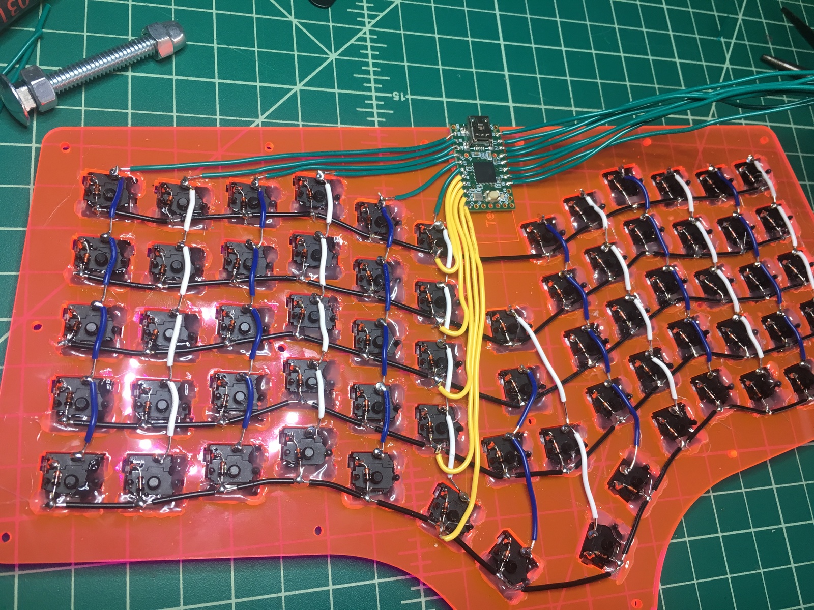
Connecting the Rows
I attached the rows first. I pretty much just pulled each wire to where it need to be, cut it to length, and stripped ~0.5” off of the end.
Then I wrapped it in a loop around the joint and soldered.
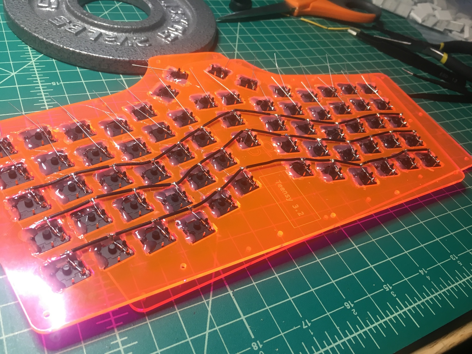
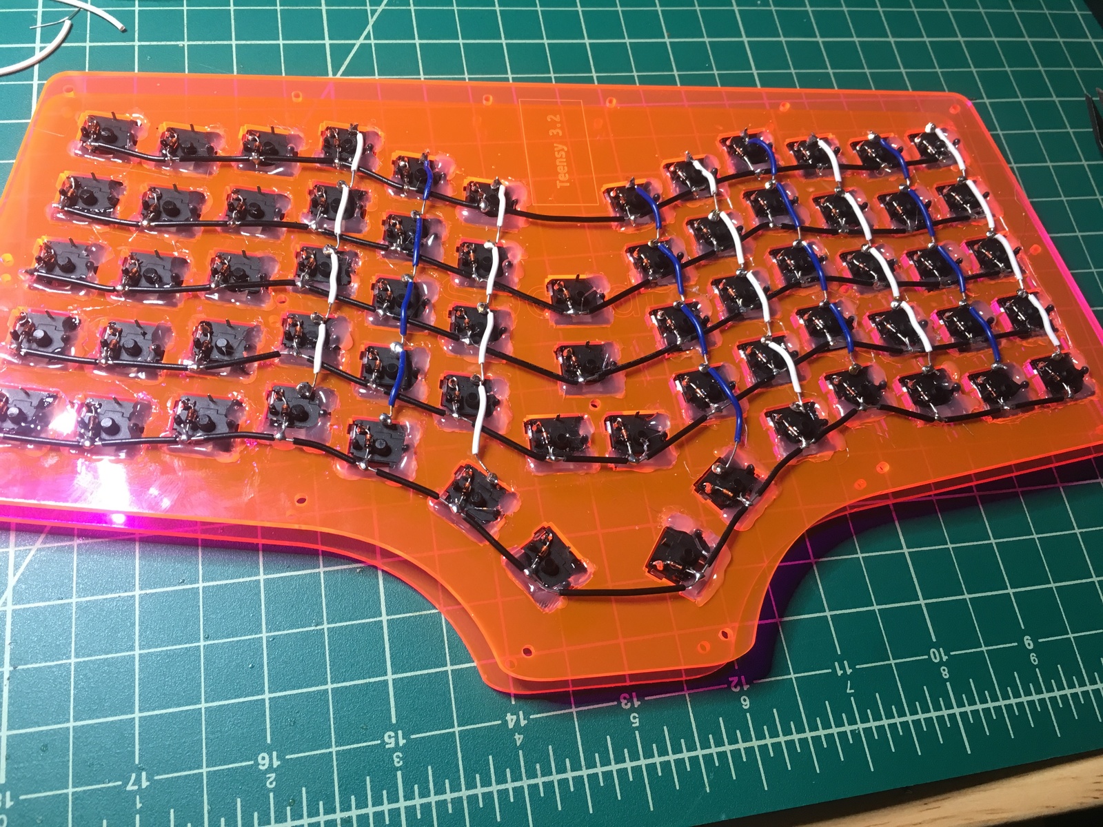
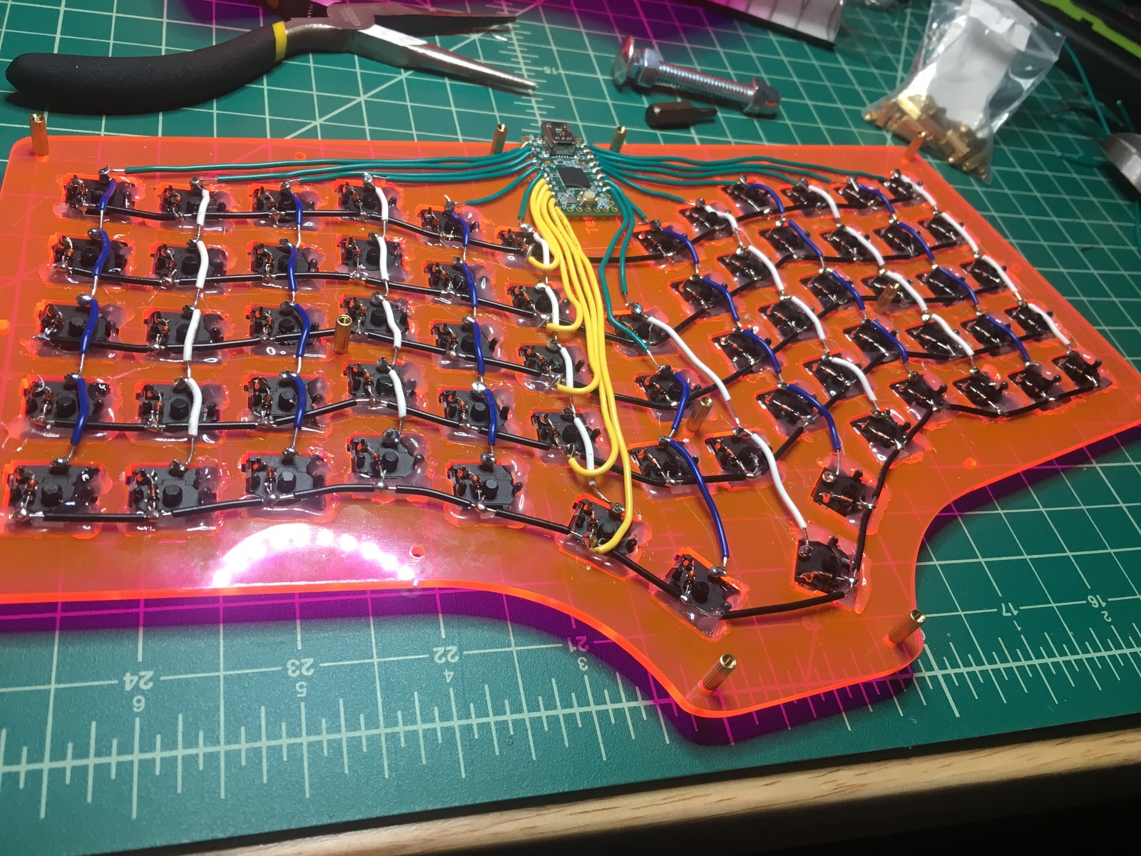
Connecting the Columns
Then I did the exact same thing for the columns.
First 6 columns:
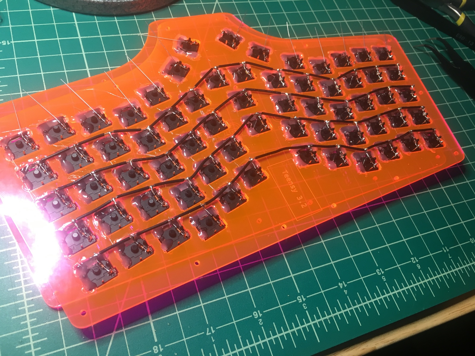
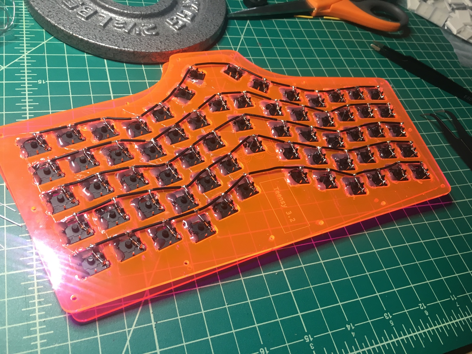
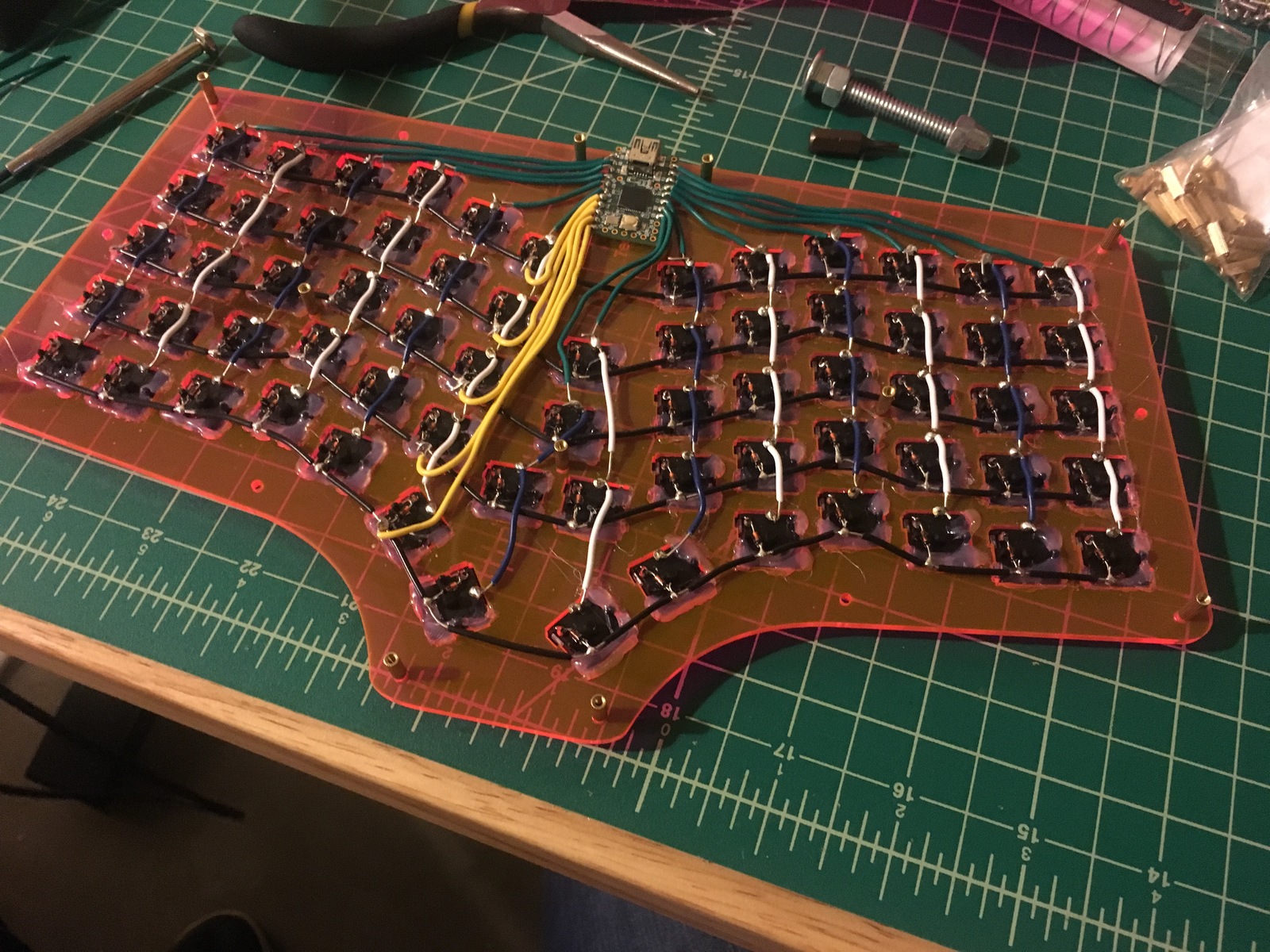
Then the rest:
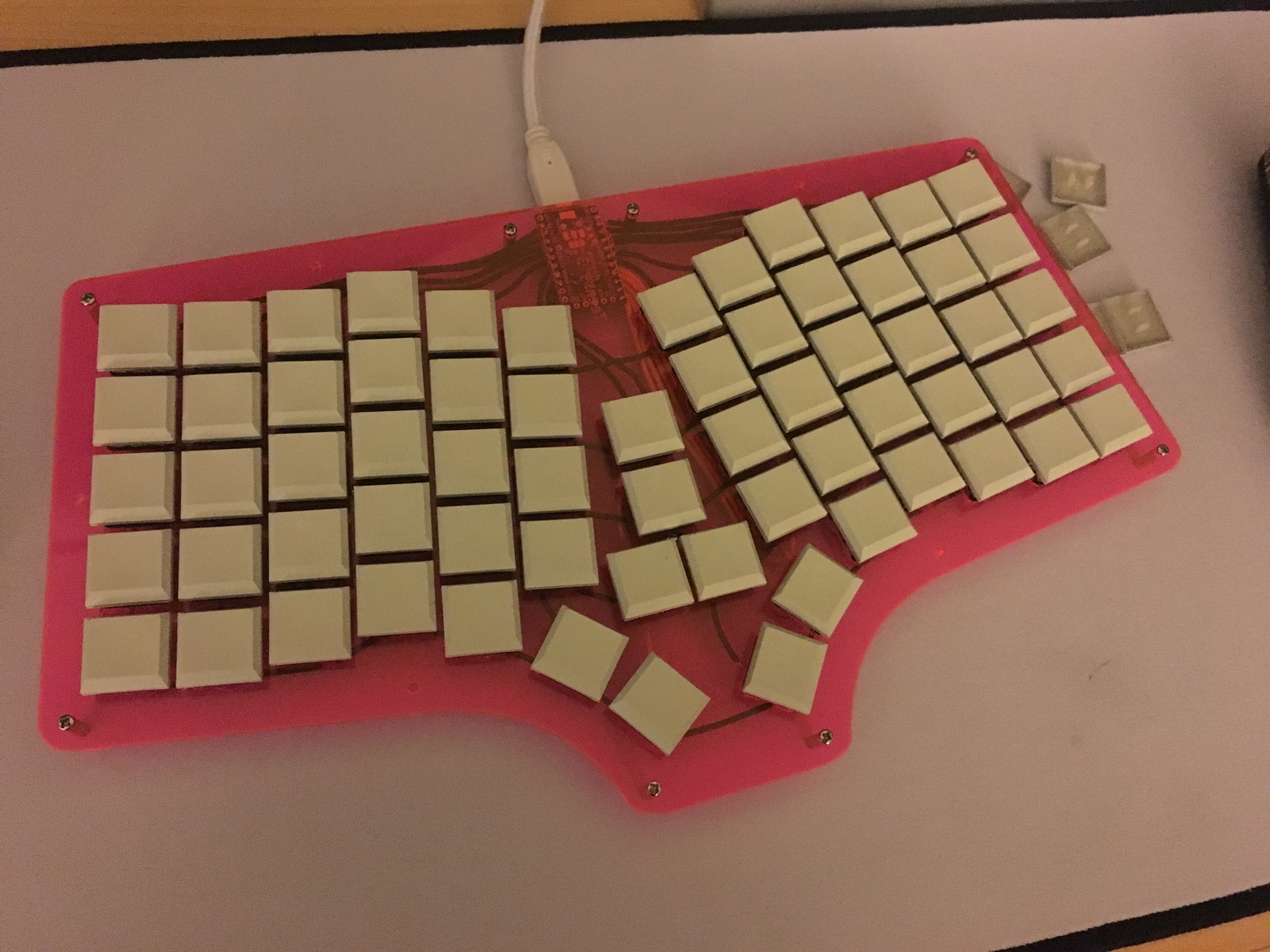
Holy shit I’m finally done soldering:
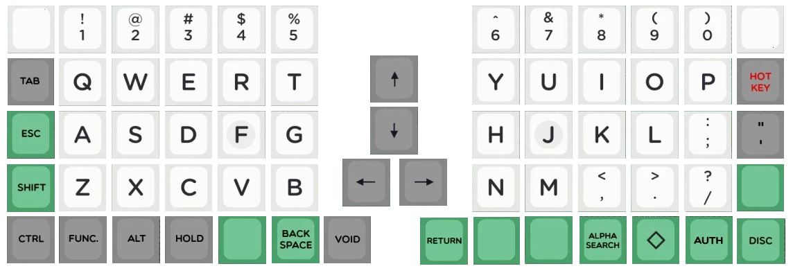
Keycaps and Firmware
Finally I put keycaps on and set up some initial firmware.